

How to Install Rock Bolts: A Complete Step-by-Step Guide

Dayang Yang
AuthorWith over 15 years of experience in the production and sales of ground anchoring and mining support products, we operate our own rock bolt and accessory manufacturing facility with stable large-scale production capacity. We are specialists in rock bolts, resin cartridges, anchor cables, bearing plates, and customized ground anchoring products for mining support and geotechnical anchoring solutions.
A reliable ground support system is not complete simply because the drill has reached the design depth. Borehole condition, compatibility between the bolt and accessories, correct grouting or anchoring procedures, and traceable installation records all affect the final support performance. For installation crews, a loss of control at any stage can disrupt later operations. For project managers and procurement teams, system compatibility and process records are equally important.
This guide explains the main stages of rock bolt installation in the order they occur on site. It also compares conventional predrilled rock bolts with self-drilling hollow bars. The content applies to common drilled rock anchoring work in tunnels, underground caverns, mine roadways, slopes, and foundation excavations.
It is important to clarify that rock bolts, rock anchors, and anchor bars are sometimes used interchangeably on projects. However, post-tensioned anchors, cable anchors, and other specialist anchorage systems usually have independent design, testing, and installation requirements. They should not be installed using a general rock bolt installation procedure.
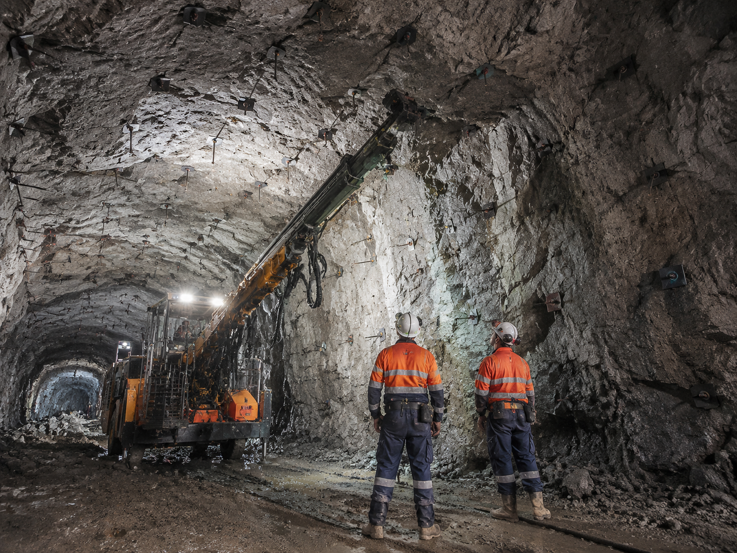
Quick Answer: What Does Rock Bolt Installation Involve?
Rock bolt installation does not follow one identical sequence for every system. In most projects, the team first verifies the approved design and method statement, completes setting out, work-face checks, and equipment preparation, then drills the hole or advances the bolt. The crew installs the specified components, completes mechanical anchoring, resin anchoring, or cement grouting, and finally finishes the bolt head, inspections, testing, and records.
Mechanical anchors, resin anchors, fully grouted rock bolts, friction bolts, and self-drilling rock bolts work differently. This article explains the construction logic at project level. It does not replace drawings, approved method statements, site safety requirements, manufacturer instructions, or acceptance criteria.
For procurement and technical evaluation teams, the key question is not which product appears more advanced. The real question is which ground support system can reliably complete every required stage under the actual geology, equipment capacity, available workspace, and project schedule.
Before Drilling: Confirm the System and Approved Method
Before drilling starts, confirm the support purpose, borehole position, drilling direction, design length, rock bolt type, accessory arrangement, and acceptance requirements for each location. The CQ Rockbolt rock bolt product center can be used to review applicable system categories. Site teams should also understand rock mass conditions, joints and fractures, groundwater, available workspace, face stability, nearby structures or utilities, and whether drilling and grouting equipment can be positioned safely.
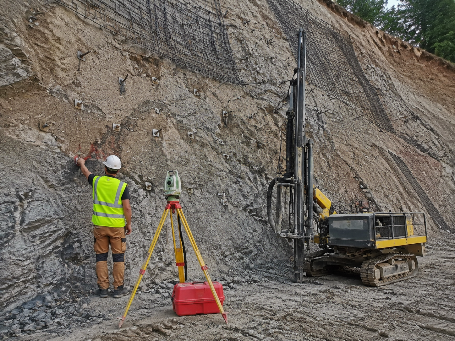
This review prevents the team from discovering too late that the next operation cannot be completed. In some ground conditions, a drilled hole remains stable until the bar is installed and grouted. In others, the borehole may ravel, reduce in diameter, hold water, or become unstable quickly. These conditions can prevent bar insertion and make continuous rock bolt grouting difficult. Where such risks exist, the drilling method, temporary support, casing arrangement, or system choice should be assessed in advance.
Before production work begins, the crew should use current drawings and the approved method, and clearly define which abnormal conditions must be reported to the responsible engineer. Exposed rock, drilling equipment, bars, bearing plates, nuts, grout materials, and connecting components should all be suitable for use. The installation sequence should follow the system requirements instead of being changed informally to recover lost time.
| Review Item | What to Confirm Before Work | Effect on Later Work |
|---|---|---|
| Rock bolt design | Borehole position, direction, length, system type, and acceptance requirements | Defines the drilling, installation, and testing route |
| Rock mass and groundwater | Fracturing, borehole stability, water return, and loss-of-return risks | Influences whether predrilled rock bolts are suitable |
| Equipment and materials | Drill rig, drill bits, bars, couplers, grouting equipment, and grout | Prevents incompatible components on site |
| Construction planning | Work face, access route, temporary protection, and record responsibilities | Supports safety and traceability |
Rock Bolt Installation Steps
1. Confirm the Design, Rock Bolt Type, and Installation Route
For each location, verify the identification number, position, design direction, specified bolt or anchor system, bearing plate, nut, and the required anchoring, grouting, tensioning, or testing method. Rock bolt is a broad category. Different anchoring mechanisms do not follow the same installation sequence and should not be checked with the same test method.
In some projects, the term rock anchor refers to the drilled rock-reinforcement system discussed in this article. In other projects, it refers to a post-tensioned or cable-based system requiring a separate procedure, such as a prestressing steel strand anchor cable. This distinction must be made before drilling begins, not after a site problem occurs.
The preparation stage should also confirm material batches and the full system arrangement. Bars, drill bits, couplers, centralizers, bearing plates, and nuts are not interchangeable standalone items. For example, a precision rolled coupler should match the corresponding bar system. These parts together form the designed ground support system, and substitutions can change connection, grouting, or load-transfer conditions.
2. Set Out the Location and Prepare Safe Drilling Conditions
Set out the work according to the approved drawings. Check the work face, drill-rig position, drilling direction, working space for handling bars, and material transport route. Tunnels, underground openings, slopes, and high cuts each have different hazards, but the common principle is the same: drilling and installation must occur in an inspected area suitable for the work.
Where loose rock, low headroom, nearby traffic, groundwater, or restricted access is present, the control measures should already be defined in the work plan. Temporary support, rockfall protection, drill-rig stabilization, lighting, ventilation, and safe worker positions are not secondary activities. They directly affect whether rock bolt installation can proceed in the planned sequence.
Before drilling, inspect whether the drill rig, flushing or grouting equipment, bars, drill bits, couplers, bearing plates, and nuts are compatible. A common site problem is not the complete absence of equipment, but a mismatched coupler, drill-bit size, or grout connection that is incompatible with the selected rock bolt system and interrupts the work midway.
3. Drill by the Approved Method or Advance the Self-Drilling Rock Bolt
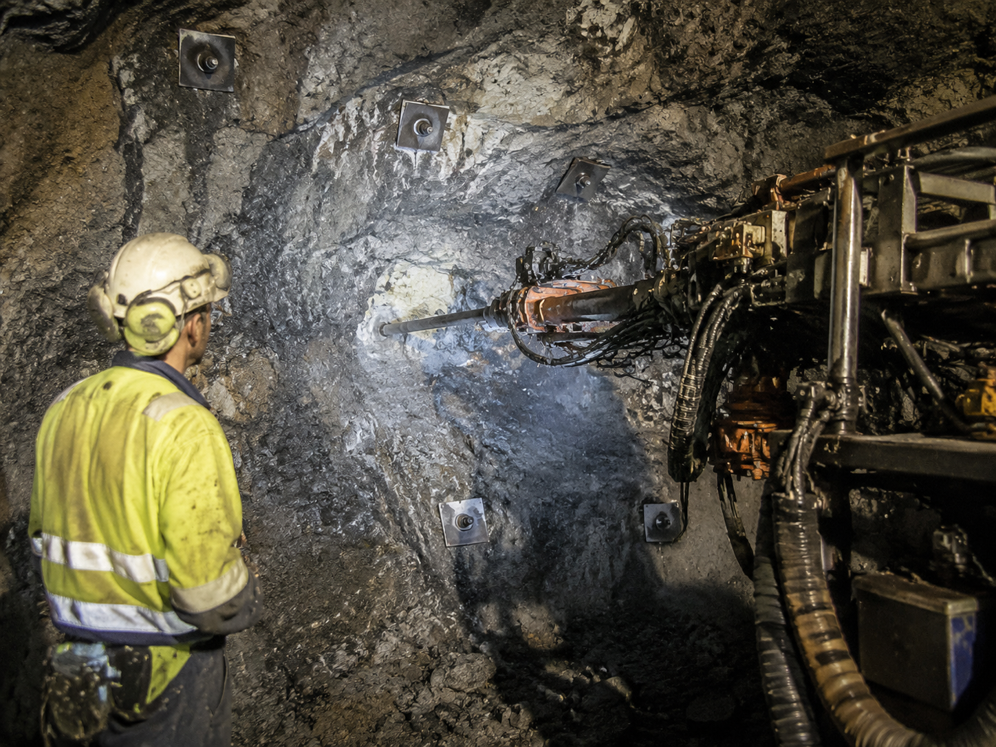
For conventional predrilled rock bolts, the objective is not only to reach the required depth. Borehole position, direction, diameter, and condition must all suit the next operation. Record unusual drilling progress, abnormal cuttings, significant loss of return, borehole instability, deviation, or rock conditions that differ from expectations, then handle them according to the project procedure.
A completed borehole does not mean the installation risk has ended. If the borehole cannot remain suitable until bar insertion, accessory installation, and rock bolt grouting are complete, the following work may have no reliable foundation. In this situation, the construction method should be reviewed instead of forcing the bar into an unstable hole or repeatedly redrilling.
For a self-drilling rock bolt route, a hollow bar with a sacrificial drill bit advances as the drill string, remains as the permanent reinforcement, and provides a grout path. This approach can reduce one transition that is highly sensitive to borehole conditions: the period between completing an open hole and starting bar installation. It is particularly useful in fractured, weak, or unstable ground.
However, self-drilling hollow bars are not an automatic solution for every ground problem. The drill bit, connection method, drilling parameters, grout delivery, bar-length combination, workspace, and design requirements must still work together. Reliable drilling, bar coupling, and grouting are more important than simply choosing a product name.
4. Install the Bar, Anchor Components, and Specified Accessories
For a conventional installation route, install the bar or complete rock bolt assembly only after the borehole has been confirmed suitable for the next step. The system may require couplers, centralizers, an anchor head, bearing plates, nuts, or other accessories. The goal is not merely to place steel in a hole. Components must be complete, correctly positioned, and capable of performing their anchoring and load-transfer roles.
Mechanical systems commonly require the anchor head to expand or engage effectively in the borehole before tightening or tensioning. For a combined system in hard-rock roadways or tunnels, the design approach of a CT combination rock bolt may be relevant. Resin systems and cement-grouted rock bolts depend even more on the relationship between the bar, the bonding material, and the installation sequence. Hard rock, weak rock, and heavily jointed rock masses have different suitability considerations.
During installation, avoid bar bending, thread damage, incomplete connections, or missing accessories. For long bars, multi-section assemblies, or restricted workspaces, installers need sufficient operating space to complete coupling and positioning in accordance with the system requirements.
5. Complete the Required Grouting, Anchoring, or Tensioning Stage
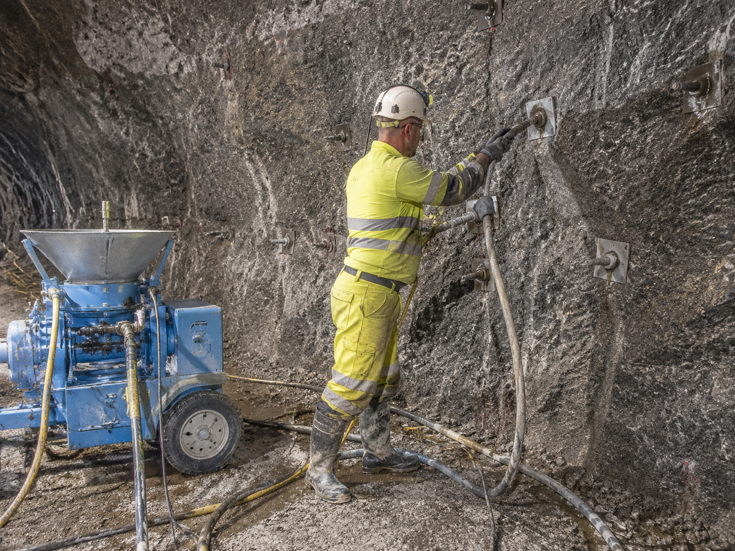
This stage is often oversimplified. A project may use mechanical anchoring, resin anchoring, full-length cement grouting, friction anchoring, or a combined drilling-and-grouting process through a self-drilling rock bolt. The sequence, material, pressure, injected quantity, curing period, and need for tensioning must be determined by the project design and system instructions.
For grouted rock bolts, the critical requirement is to complete the operation continuously according to the specified method and promptly record interruptions, grout loss, abnormal return, or other changes. Grout quality affects load transfer between the bar, grout body, and surrounding rock. Grouting is not an optional finishing activity; it is part of the anchorage system itself.
Do not directly copy grout parameters, tension loads, or test loads from one project to another. Ground conditions, bar type, borehole diameter, design objectives, and specification requirements can vary substantially. The project team should use the specific rock bolt design and acceptance criteria for the work in question.
6. Complete the Bolt Head, Required Checks, and Installation Records
Complete the bearing plate, nut, sealing, corrosion protection, and other bolt-head details required by the design. Where tensioning, torque checks, pull-out tests, verification tests, grout-quality checks, or monitoring are required, follow the stated procedure and ensure that test conditions and results are traceable.
Every installed rock bolt should have a clear record. Typical information includes identification number, location, direction, drilling or advancement details, system components, changed ground conditions, anchoring or grouting information, test results, deviations, and corrective actions. Records are not simply paperwork. They allow the team to verify whether the actual installation matches the design and approved method.
When abnormal conditions occur, records made at the time are more reliable than later recollection. Borehole changes, drilling interruptions, grout anomalies, material substitutions, and test deviations often provide the information needed to decide whether later support measures should be adjusted.
Two Installation Routes: Conventional Predrilled Rock Bolts and Self-Drilling Hollow Bars
| Comparison Item | Conventional Predrilled Rock Bolt or Rock Anchor | Self-Drilling Hollow Bar System |
|---|---|---|
| Basic sequence | Drill the borehole, then install the specified bar and complete anchoring or grouting | Advance a hollow bar with a drill bit; the bar remains as reinforcement and can provide the grout path |
| Main question | Can the borehole remain workable through bar insertion and grouting? | Can drilling, bar connections, and grouting be controlled under the system method? |
| When to assess | Where ground allows each stage to be completed separately and reliably | Where borehole stability or transition between stages creates a risk worth evaluating |
| Essential controls | Design, borehole condition, correct anchoring or grouting, bolt head, and acceptance records | Design, compatible equipment, connections, grouting, bolt head, and acceptance records |
The value of self-drilling rock bolts is that they can reduce one construction transition that is highly dependent on borehole condition. They do not replace all conventional rock bolts or rock anchors. This integrated route offers a clear advantage only when geology, design, workspace, and approved construction methods support it. System selection for mining and tunnel applications can also be assessed with reference to underground mine support systems.
Key Quality-Control Points During Installation
| Stage | What to Check or Record | Why It Matters |
|---|---|---|
| Before work | Current design, method statement, system components, equipment condition, and safety conditions | Prevents use of an incorrect system or outdated method |
| Setting out and drilling | Identification number, borehole position, direction, drilling response, borehole condition, and water return | Shows whether actual ground conditions differ from expectations |
| Bars and accessories | Bar specification, couplers, drill bits, anchor components, bearing plates, and nuts | Confirms that the installed assembly matches the approved arrangement |
| Anchoring or grouting | Installation method, continuity of work, and required project records | Provides facts for abnormal-condition assessment and quality traceability |
| Completion and acceptance | Bolt-head details, testing, deviation handling, and final records | Supports project acceptance and later maintenance |
This table is a framework for site communication and process control, not a universal acceptance form. Dimensions, torque values, grout parameters, test loads, and pass-or-fail criteria must come from the project requirements.
Common Mistakes
1. Treating Every Rock Bolt as the Same Product
Rock bolt is a product category, not a single installation method. If the anchoring mechanism and system details are not confirmed first, the team may use the wrong steps, accessories, or testing method and reduce the actual performance of the ground support system.
2. Focusing Only on Drilling and Ignoring Borehole Condition Between Stages
Completing the borehole does not mean the installation risk is finished. For conventional predrilled rock bolts, the borehole must remain suitable until bar insertion and grouting are complete. If this cannot be ensured, the method should be reassessed instead of forcing the next step.
3. Treating Self-Drilling Rock Bolts as the Default Answer for All Difficult Ground
Self-drilling hollow bars can combine drilling, grouting, and reinforcement in some conditions, but they still have equipment, connection, corrosion-protection, design, and acceptance requirements. They are an option to assess against project conditions, not a universal replacement.
4. Using a General Article as a Method Statement
An industry article can explain the sequence of rock bolt installation and the questions that should be asked. It cannot define the borehole diameter, drilling angle, torque, grout parameters, or testing requirements for a particular project. These details must come from approved drawings, project specifications, and system instructions.
5. Completing Records Only After the Work Is Finished
Abnormal drilling, borehole changes, grout interruptions, and component substitutions are most valuable when they are recorded as they occur. A later rock bolt installation record often cannot accurately reconstruct site conditions and can weaken the reliability of quality traceability.
Conclusion
Reliable rock bolt installation starts with confirming the design, rock conditions, and construction route. It continues through drilling, installation, anchoring, and inspection, and ends with complete records that create a verifiable engineering result. Whether the project uses conventional predrilled rock bolts or self-drilling rock bolts, the key is whether every stage can be completed reliably under approved conditions.
For contractors and procurement teams, system selection should consider ground compatibility, matching components, equipment capacity, workspace, grout control, and acceptance requirements. The CQ Rockbolt homepage provides access to products and technical resources that can support further project-specific evaluation. Clarifying these factors before work begins is usually more effective than reacting to borehole, material, or workflow problems during construction.
Frequently Asked Questions
Are Rock Bolts and Rock Anchors Installed the Same Way?
Some drilled rock bolt and rock anchor systems use similar procedures. However, post-tensioned anchors, anchor cables, and cable systems may require independent design, tensioning, locking, and testing procedures. Confirm the design definition of the system before choosing the installation method.
Do All Rock Bolts Require Grouting?
Not necessarily. Mechanical anchoring, resin anchoring, friction anchoring, and full-length grouted rock bolts use different working mechanisms. Whether grouting is required depends on the specific system and project design requirements.
Do Self-Drilling Rock Bolts Need a Predrilled Hole?
Usually not. A self-drilling rock bolt is generally advanced with a hollow bar and drill bit at the same time. After drilling, the bar remains as the reinforcement element and can be used to deliver grout. Actual work should still follow the approved procedure for that system.
How Can You Determine Whether a Rock Bolt or Rock Anchor Has Been Installed Properly?
Use the project design, construction specification, and acceptance requirements to check borehole position, bars and accessories, anchoring or grouting records, bolt-head details, required torque checks, pull-out tests, and verification-test results. A single inspection item is usually not enough to confirm overall installation quality. For specific geology, dimensions, or procurement requirements, contact CQ Rockbolt to submit project requirements and obtain matching product and system information.
Related News
Other news you might be interested in

Deep Mining & Long-Service-Life Tunnel Support: Key Factors for Rock Bolt Corrosion Protection and Long-Term Durability
A buyer can receive two quotations for “corrosion-resistant rock bolts” and still be unable to compare them. One may refer to a galvanized bar. Another may include epoxy-coated bars, sealed couplers, protected anchor heads, and a specified grout cover. Both descriptions sound protective, but they do not cover the same parts of the support system or provide the same kind of evidence.

Threadbar Coupler Compatibility: Drawings, Threads and Test Evidence Before Ordering
A threadbar coupler can look like a straightforward steel sleeve with a thread at each end. In practice, compatibility depends on the bar system, the complete joint arrangement and the evidence supplied for the exact product.A matching nominal diameter is not enough. Similar-looking couplers may use different thread forms, tolerances, engagement lengths or material conditions. They may also serve different purposes in a prestressing anchor, a mechanical reinforcement splice or another load-carrying assembly.Before accepting a quotation, establish what the coupler connects, which drawings control the joint and what the test report actually proves. These checks help buyers compare offers on the same technical basis.
Want to know more?
Get in touch with us for more information about our services and products.