

How to Install Self-Drilling Rock Bolts in Tunnels?

Dayang Yang
AuthorWith over 15 years of experience in the production and sales of ground anchoring and mining support products, we operate our own rock bolt and accessory manufacturing facility with stable large-scale production capacity. We are specialists in rock bolts, resin cartridges, anchor cables, bearing plates, and customized ground anchoring products for mining support and geotechnical anchoring solutions.
Installing a self-drilling rock bolt in a tunnel is a continuous process, not a bolt dropped into a pre-drilled hole. The hollow threaded bar is the drill string, the grout channel and the final reinforcement. The bit cuts the hole and remains downhole; couplers extend the string; grout travels through the bar and fills the annulus; the plate and nut transfer load to the tunnel surface.
That is why installation quality depends on more than operator skill at the rig. It depends on the bit-to-bar match, thread condition, grout mix, pump settings, hole alignment and the sequence used in the tunnel cycle. The steps below explain the normal sequence for a grouted self-drilling system. Resin-based or simultaneous drill-and-grout systems follow their own approved method. In every case, the project's support design, method statement and the manufacturer's instructions for the exact product take precedence over this general guide.
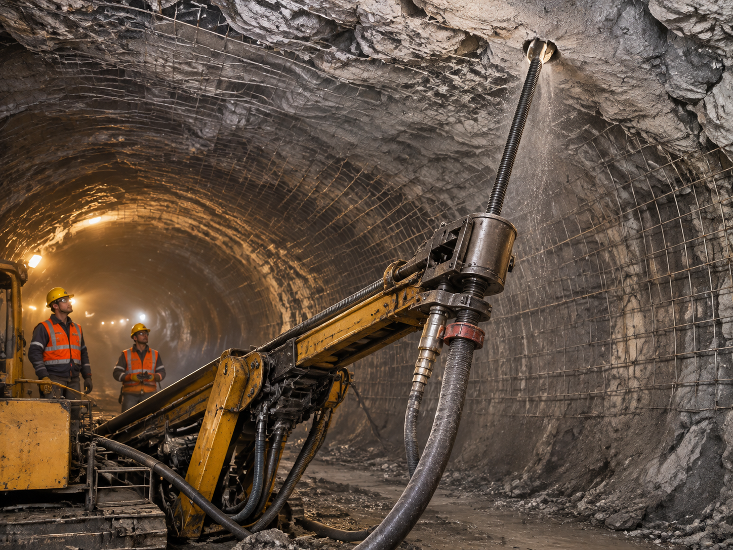
The installation sequence at a glance
- Confirm the support design, bar and bit combination, grout system, rig and services.
- Mark the hole position, angle and depth.
- Inspect and assemble the bar, sacrificial bit, coupler, grout adapter, plate and nut.
- Align the rig and connect the flushing or grouting line.
- Drill to the specified depth, adding bar sections where required.
- Inject grout through the hollow bar, or drill and grout simultaneously where approved.
- Fit the bearing plate and nut and apply the specified pre-tension.
- Record the installation, inspect the bolt and carry out the project pull tests.
The rest of this article explains what each step requires and where tunnel conditions change the decision.
Why tunnel installation needs a controlled sequence
A tunnel bolt is installed in a constrained, moving environment. The face, crown or rib may be overhead; access may be limited by a platform, arch or conveyor; water may be running from the hole; and the support cycle may be competing with excavation, mesh, shotcrete and ventilation.
In broken ground, the hole may not stay open long enough for a separate insertion step. That is the practical reason self-drilling anchor bolts are used: the bar remains in the hole while drilling, so there is no open hole waiting for a bolt. In stable rock, a conventional drill-and-insert bolt may still be the simpler choice. The installation method should follow the ground and the design, not a product preference.
Tunnel installation also has a sequencing issue. A bolt that is drilled but not grouted, or grouted but not plated, is not a completed support element. The method statement should define who completes each step, how the hole is identified and what happens if the cycle stops. On a tunnel site, an incomplete bolt can be buried by mesh or shotcrete before anyone records it.
Before drilling: confirm the inputs that control the installation
The approved support design
Confirm the bolt type, length, diameter, pattern, angle and design load from the approved drawings. Do not ask the supplier or the drilling crew to select the support pattern from a product catalogue. The installation team needs the revision that is current at the face, not a superseded drawing.
Also confirm how the bolt fits the rest of the support system: mesh, straps, steel arches, shotcrete, cable bolts or forepoling. The installation sequence may need to change so that the plate sits correctly and the bolt is not damaged by later work.
The bar, bit and connection schedule
For each hole, confirm the bar model, length, thread, coupler, bit type and bit diameter. These items form a system. A bit that is visually similar but has the wrong diameter changes the grout annulus. A coupler from another thread system may start to engage but may not transmit drilling energy or carry load as intended.
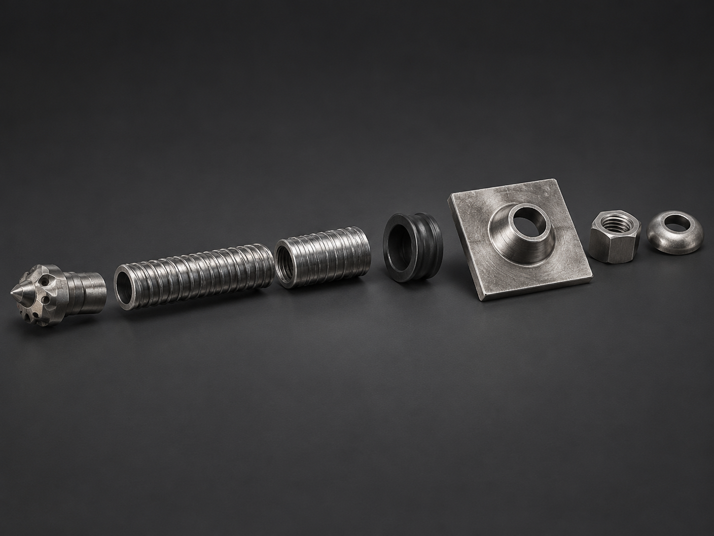
Check the internal bore for blockage, the external thread for damage and the bit for correct type and condition. Confirm that the grout outlets at the bit are open. If the bar or bit has been stored on site, check for rust, bent sections, crushed threads and contamination.
The grout or resin system
Confirm the approved grout or resin, its mix or ratio, working time, injection pressure and volume. These are project-specific values. The product page may give a general pressure range, but that is not a site setpoint. The method statement should state how the mix is measured, how long it remains usable and what to do if the grout starts to set in the line.
For cementitious grout, check the mixer, water measurement, pump, hoses, pressure gauge and return arrangement. For resin systems, check the cartridge or pump system, the working time and the compatibility with the bar and ground. Do not substitute one system for another without technical review.
The rig and working platform
Confirm that the rig can deliver the required rotation, feed, torque and flush or grout connection at the hole position. Check the feed length against the bar length and available headroom. In a tunnel crown, the platform may limit the angle or the length that can be handled in one pass.
Check that the flushing or grout line can reach the collar without a sharp bend or a suspended load. Secure hoses and cables so they do not catch on the rig, the platform or the bar. The operator should have a clear view of the collar and a safe position outside the rotating-string zone.
Services, access and emergency arrangements
Confirm water, air, power, ventilation and drainage. In an overhead hole, water and grout can fall onto the platform and walkway. Provide containment and a safe route for the return line. Confirm the communication method between the rig operator and the grout operator, especially when the pump is some distance from the face.
The work area should be assessed for ground stability before anyone stands under the crown. Installation does not make an unsupported roof safe. The site's ground control and working-at-height procedures apply.
Step-by-step installation
Step 1: Mark the hole position, angle and depth
Mark the collar position and the designed angle using the project's reference system. In a tunnel, that may be a laser, total station, jig or a marked profile. Check the reference against the tunnel contour; a line that is correct at one chainage may not be correct at the next.
Mark the required drilled depth, not only the bolt length. The bar needs the specified embedment and enough projection at the collar for the plate, nut and connection. Confirm the projection from the approved detail rather than guessing on site.
Record the hole number before drilling. The number should stay with the hole through drilling, grouting, plating and testing.
Step 2: Assemble the bar and bit
Fit the specified sacrificial bit to the leading end of the bar using the supplier's connection. Confirm that the bit is fully engaged and that the grout outlets are not blocked by the connection.
If the hole is deeper than one bar, plan the coupler positions before drilling. Clean the threads and check that the coupler is the correct type. Do not use a coupler as a hammer or a lifting point, and do not force a damaged thread.
At the collar end, fit the specified grout stopper or seal and the adapter or swivel required for the flushing or grouting line. The connection must suit the bar thread and the pump or rig. A loose adapter can leak grout, reduce pressure at the bit and create a mess at the collar.
Step 3: Set the rig and connect the line
Align the rig to the marked angle. Bring the bit to the collar and check the alignment before rotation. A small error at the collar becomes a larger error at depth, especially in a long hole.
Connect the water or air flush, or the grout line, according to the approved method. Open the line and check for flow before drilling. Confirm that the pressure gauge is readable and that the return path is clear. If the method uses simultaneous drilling and grouting, the grout line, pump and return arrangement must be ready before the bit enters the rock.
Step 4: Drill to the specified depth
Start the hole with controlled feed and rotation. Establish the collar, then adjust feed and rotation to the ground. Watch the flush return, penetration rate, vibration and any change in resistance. A sudden loss of return, a jump in pressure or a change in penetration can indicate a broken bit, a blockage or a change in ground.
Add bar sections with the specified couplers when the rig feed or hole depth requires it. Make up each connection fully, following the supplier's procedure. Do not allow the string to rotate with a partially engaged coupler. Keep the threads clean; cuttings and grout on the threads can prevent full engagement.
Drill to the marked depth. In unstable ground, do not stop unnecessarily with the bar in a partly drilled hole. If the method calls for continuous drilling and grouting, keep the sequence moving. If drilling must stop, follow the approved contingency for hole stability and equipment failure.
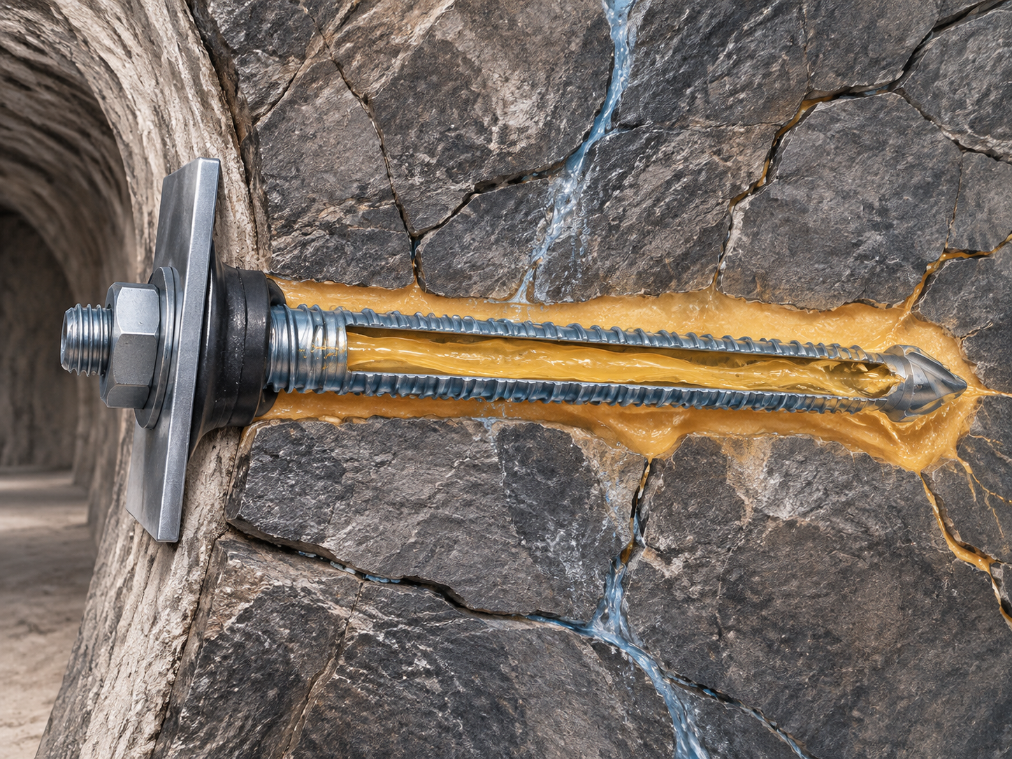
Step 5: Grout through the hollow bar
This is the step that turns the bar into an anchored element. The grout travels down the internal bore, exits at the bit, fills the annulus from the bottom of the hole upward and bonds the bar to the rock. The collar stopper or seal prevents backflow and helps maintain pressure.
Some systems drill with water or air flush and then inject grout through the same bar. Others are designed for simultaneous drilling and grouting. CQ describes its self-drilling hollow grouting rock bolt as integrating drilling, grouting and anchoring, with the bar interior used as the grouting channel. Follow the approved method for the exact system; do not assume that every self-drilling bar uses the same sequence.
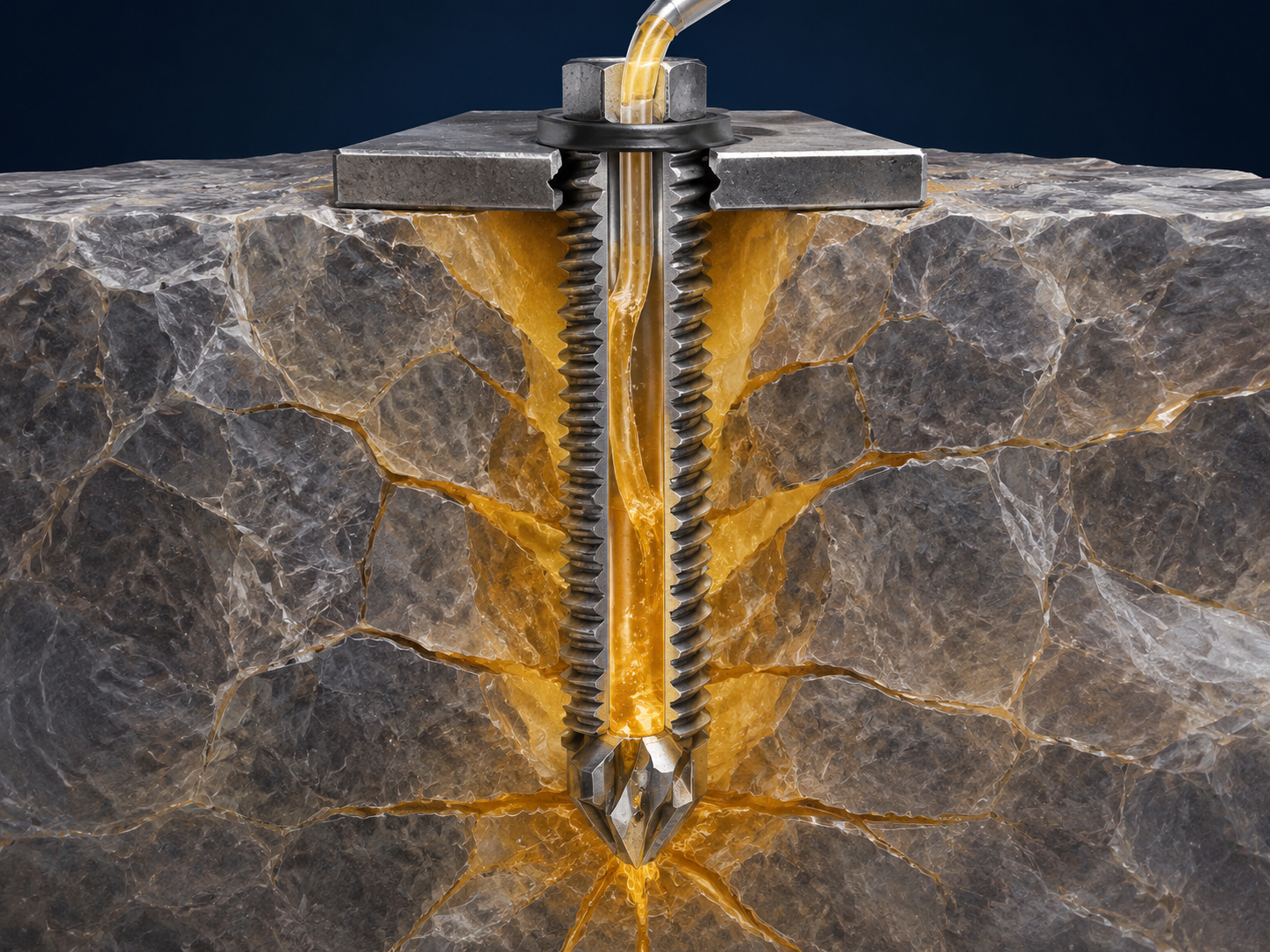
Before injection, confirm the grout mix, working time and pump setting. Start at a controlled pressure and watch the collar, the return and the pressure gauge. CQ's published general guidance for conventional grouting pressure is 0.5–2.0 MPa, adjusted for surrounding rock, grout type and design requirements. That range is a reference, not a substitute for the project's approved pressure.
Stop when the specified volume has been injected and the required return or pressure condition is met. If grout appears at the collar, if the volume is far above or below the expected value, or if pressure cannot be maintained, stop and investigate. Do not continue pumping against a blocked line or an open leak.
Step 6: Fit the bearing plate and nut
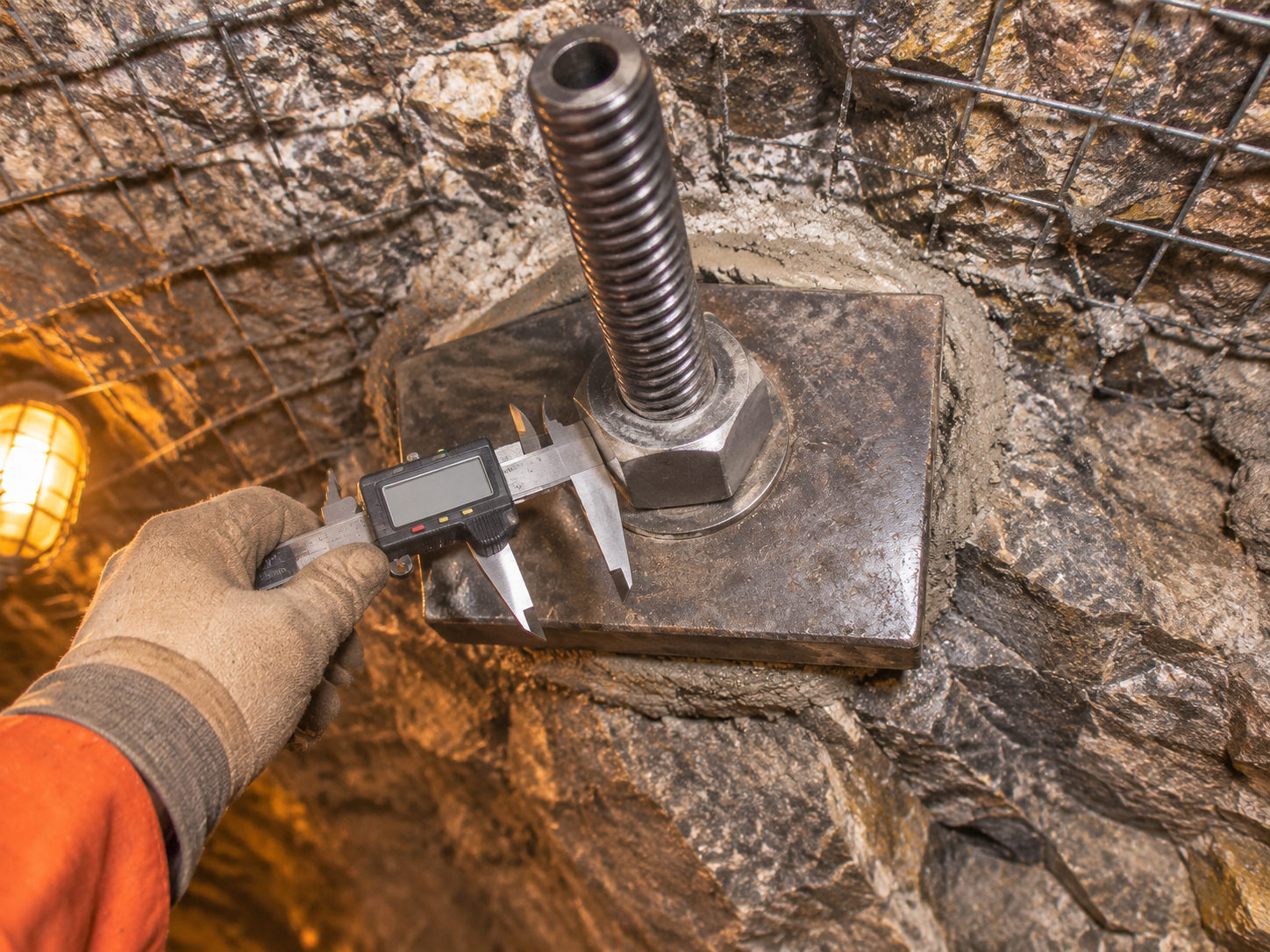
Prepare the collar area so the plate can seat on the rock or on the specified bearing surface. Fit the plate and nut with the specified washer or spherical seat. Check that the nut engages the full specified thread length and that the plate is not bridging a hollow or a loose block.
Apply the specified pre-tension only when the method statement permits. CQ states that the bearing plate and nut apply pre-tightening force and allow the bolt to provide active support; the actual timing and torque must still follow the approved installation procedure and the grout or resin condition. Do not use the nut to pull a misaligned bar straight, and do not over-tighten a plate onto an uneven surface.
If mesh, straps or arches are part of the support, install them in the approved order. The plate should bear on the intended surface, not on a deformed mesh or a loose block.
Step 7: Finish, identify and record
Remove excess grout and clean the exposed thread only in the way the approved method allows. Do not cut the bar, bend it or damage the coating to make the plate fit. If the bar must be cut, confirm the acceptable cut position and the corrosion protection for the cut end.
Tag or mark the installed bolt with the hole number. Record the bar model, length, bit type, coupler positions, grout batch, pressure, volume, installation time and any deviation. The record should let a later inspector find the bolt and compare it with the design.
Step 8: Inspect and test
Inspect the installed bolt for plate contact, nut engagement, grout leakage, exposed bar and coating damage. Check that the bolt is at the specified position and angle and that the plate is not loose.
Carry out pull tests at the frequency and acceptance values in the project specification. A pull test checks the installed anchor in the ground; it does not replace the bar's material certificate or the installation record. Test results should be reviewed as a set. A cluster of low results may point to a grout problem, a depth problem or a change in ground, not simply a bad bar.
CQ self-drilling rock bolt configurations
CQ publishes the following configurations for its self-drilling hollow grouting rock bolt. The values are product-page data; confirm the exact model, thread, length, finish and documentation against the order and the project specification.
| Model | Nominal diameter (mm) | Inner diameter (mm) | Tensile strength (MPa) | Yield strength (MPa) | Standard length (m) | Matching drill bit diameter (mm) |
|---|---|---|---|---|---|---|
| R25 | 25 | 13 | ≥550 | ≥350 | 2 / 3 / 4 | 32 / 38 / 42 |
| R32 | 32 | 17 | ≥550 | ≥350 | 2 / 3 / 4 / 6 | 42 / 45 / 51 |
| R38 | 38 | 21 | ≥550 | ≥350 | 3 / 4 / 6 | 51 / 57 / 64 |
| R51 | 51 | 28 | ≥550 | ≥350 | 3 / 4 / 6 | 64 / 76 / 89 |
| T76 | 76 | 42 | ≥550 | ≥350 | 3 / 4 / 6 | 89 / 102 / 114 |
The nominal bar diameter is not the drilled hole diameter. The matching bit diameter creates the hole and the annulus around the bar. The correct combination depends on the specified hole, ground condition and grout system. A larger bit does not automatically improve the anchor; it changes the grout volume and the annulus.
CQ also states that multiple bars can be extended with coupling sleeves for deep-hole support, with connection strength no less than the bolt body. That is a product statement for the offered system; the project should still confirm the coupler type, make-up procedure and any test evidence for the exact configuration.
Common installation problems and how to prevent them
| Problem | Likely cause | Practical control |
|---|---|---|
| Bit does not match the bar or hole | Wrong bit diameter or connection | Check the bit against the bar drawing and the specified hole diameter before drilling |
| Bar will not advance | Blocked bore, worn bit, wrong feed or collapsed ground | Check flush, bit condition and rotation; follow the approved contingency |
| Coupler will not make up | Damaged or dirty thread, mismatched coupler | Clean and inspect threads; use the specified coupler; do not force |
| Grout does not reach the collar | Low volume, leak, blockage or wrong injection sequence | Monitor pressure and volume; check connections and grout outlets; stop and investigate |
| Grout leaks at the collar | Poor stopper seal or oversized collar | Fit the specified stopper; prepare the collar; control pressure |
| Plate does not seat | Uneven rock, wrong plate, damaged thread or misaligned bar | Prepare the bearing surface; use the specified plate and spherical seat; do not bend the bar |
| Coating damaged during installation | Handling, thread make-up or grout hose abrasion | Protect the bar, use correct tools and repair the coating as approved |
| No traceable record | Hole number lost during the cycle | Mark the hole before drilling and record each stage |
Tunnel-specific controls
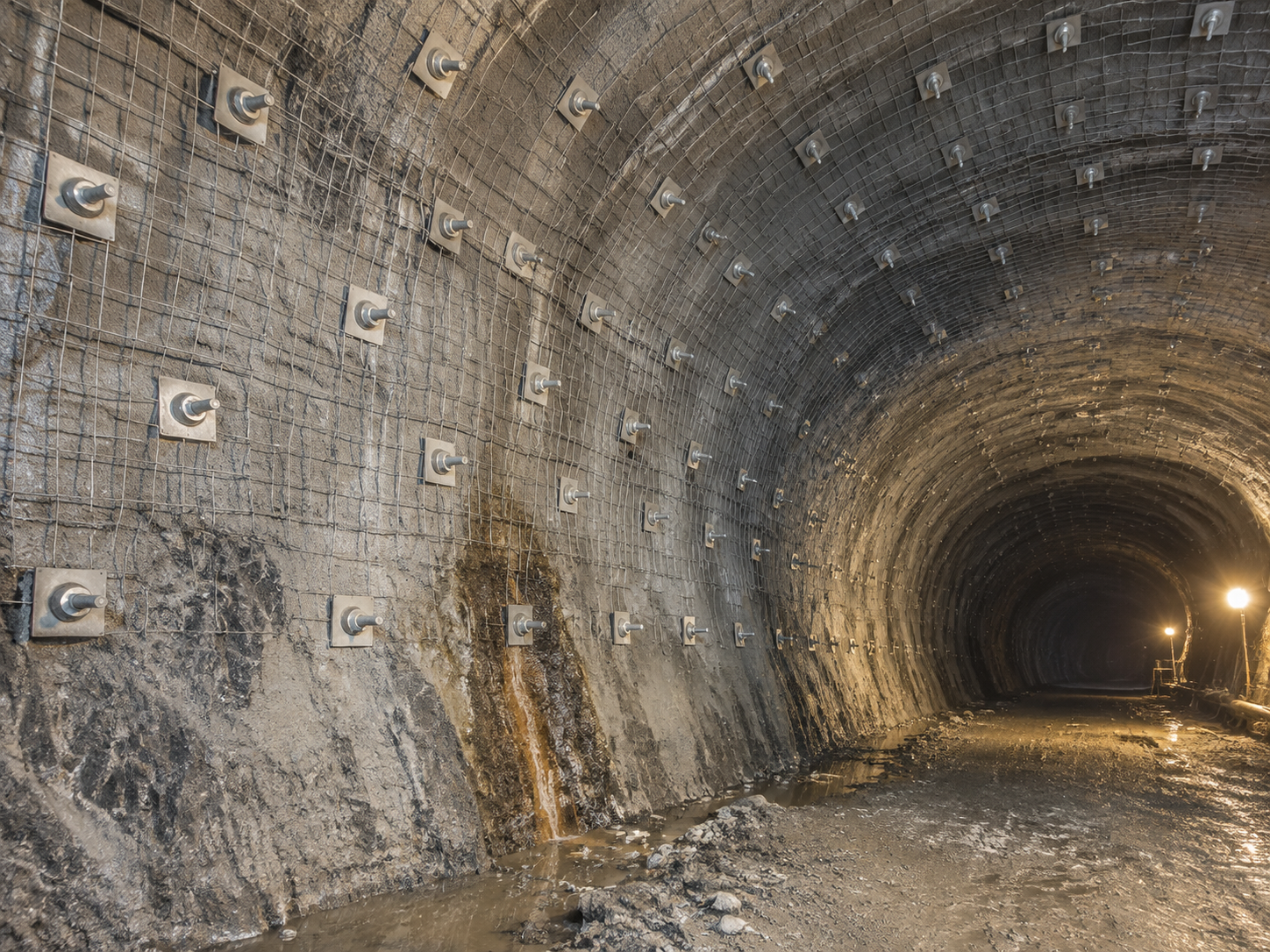
Crown and overhead holes. Use a stable platform with edge protection. Secure the grout and flush hoses so they cannot fall or catch the rotating string. Keep the operator out of the line of the bar and the bit. Confirm the roof is supported before working underneath it.
Weak, fractured or running ground. The advantage of self-drilling is continuity. Avoid unnecessary stops, keep the flush or grout sequence as approved, and watch for changes in return and grout take. A sudden increase in grout volume may indicate a connected fracture or an oversized hole; a sudden decrease may indicate a blockage.
Water inflow. Water can dilute or wash out grout and can change the working time. Confirm the approved grout for wet conditions, control the inflow where possible and check that the grout is not being displaced before it sets. Do not assume that a grout that works in a dry hole will perform the same way in a flowing hole.
Sequencing with mesh, shotcrete and arches. Install the bolt, plate and nut in the order that lets the plate bear correctly. Do not cover an untested or incomplete bolt with mesh or shotcrete without recording it. If the support cycle stops, identify the open holes and the partial installations before the next shift.
Corrosion protection. CQ's product page describes high-strength alloy structural steel with anti-rust surface treatment. For a tunnel with groundwater, chlorides or a long design life, confirm the required coating or protection from the project specification. Protect the coating during handling and repair damage only with an approved method.
Temperature and working time. Hot tunnel conditions can shorten grout working time; cold conditions can delay strength gain. Measure the grout temperature and follow the approved mix and working time. Do not mix a larger batch than the crew can place within the usable period.
What good installation records look like
A useful record is short enough to complete at the face and specific enough to support an investigation. It should include:
- Hole number, chainage, position, angle and drilled depth.
- Bar model, length, batch or heat number and coating.
- Bit type and diameter, coupler type and positions.
- Grout or resin batch, mix, temperature, pressure, volume and return.
- Installation date, shift, operator and rig.
- Plate and nut installation, pre-tension where required.
- Pull-test result and any deviation or repair.
These records are also useful for the next project. They show what was actually installed, not only what was specified.
What to send for a project-specific installation review
If you are planning self-drilling rock bolts for a tunnel, send a single technical package rather than a one-line request for a price. Include:
- Tunnel application and location: crown, rib, face, portal, fault zone or rehabilitation.
- Ground condition: rock type, strength, fracturing, water, squeezing or swelling, and expected hole stand-up time.
- Support design: bar length, diameter, pattern, angle, design load and interaction with mesh, shotcrete or arches.
- Hole and bit requirement: specified hole diameter, drilled depth and any project-specific bit restriction.
- Equipment: rig make and model, feed length, rotation, torque, adapter and grout pump.
- Grout or resin: approved material, mix or ratio, working time, pressure and volume.
- Corrosion and service life: environment, temporary or permanent support, and required coating.
- Commercial and documentation: quantity, delivery point, test plan, acceptance records and required document language.
CQ Rockbolt's self-drilling hollow grouting rock bolt page lists the R25, R32, R38, R51 and T76 configurations, matching bit diameters and standard lengths. For a project review, send the tunnel and support details to CQ so the available bar, bit, coupler, plate, nut and documentation can be confirmed against the exact configuration.
If you are still comparing installation methods, the guide to self-drilling vs. pre-drilled hollow-core rock bolts explains the component and equipment differences. If the tunnel is in weak or broken ground, the article on why self-drilling anchor rock bolts are used in mining provides the ground-support context.
The goal is not to complete the fastest hole. It is to install a bolt that is in the right place, fully grouted, correctly plated and traceable to the design. Those controls are what separate reliable tunnel rock bolts from support elements that merely look installed.
Related News
Other news you might be interested in

Self-Drilling Anchor Bolts for Water-Conveyance Tunnel Reinforcement
Self-drilling anchor bolts are useful for water-conveyance tunnel reinforcement when broken or water-bearing ground makes conventional drill-and-insert bolting difficult. By using a hollow threaded bar as both the drilling member and the permanent reinforcement, the system removes the separate bolt-insertion step and provides a channel for grouting through the same bar.For a water-conveyance tunnel, that installation advantage matters. Headrace, tailrace, diversion, irrigation and water-supply tunnels can pass through fault zones, weathered rock, weak interlayers and interconnected fractures. Groundwater may enter the excavation, boreholes may deteriorate after drilling, and support must be coordinated with drainage, waterproofing and the final lining.

What Is a Split Set Mining System and How Is It Different from Other Rock Bolts?
A split set is often described as a rock bolt, but in mining it is more useful to think of it as a support system. The steel tube is the most visible part. The way it performs also depends on the drilled hole, the bearing plate, the installation adapter, the drilling equipment, the surface support and the checks made underground. That distinction matters when a project compares rock bolts. Two quotations can list a similar diameter and length, yet propose different load-transfer mechanisms, different hole requirements and different installation procedures. A split set is not a resin bolt with the resin removed. It is not a mechanical expansion-shell bolt, a self-drilling hollow bar, a water-inflatable tube or a cable bolt. Each product family solves a different part of the ground-support problem.
Want to know more?
Get in touch with us for more information about our services and products.