

How do concrete anchor bolts improve foundation stability?

Dayang Yang
AuthorWith over 15 years of experience in the production and sales of ground anchoring and mining support products, we operate our own rock bolt and accessory manufacturing facility with stable large-scale production capacity. We are specialists in rock bolts, resin cartridges, anchor cables, bearing plates, and customized ground anchoring products for mining support and geotechnical anchoring solutions.
A concrete anchor bolt is a small part of a foundation, but it decides whether the foundation and the structure above it behave as one system. The bolt does not make the concrete stronger or the soil stiffer. It provides a controlled load path between the steel structure, the base plate, the concrete, and—when the anchor is designed to reach it—the deeper ground.
In this article, the term covers cast-in anchor rods, post-installed mechanical or adhesive anchors, and post-tensioned bars or strand anchors used to tie a structure or foundation element into concrete.
That distinction is the key to answering the question. Anchor bolts improve foundation stability by resisting uplift, shear and overturning, maintaining clamping force, helping to distribute concentrated loads, and tying the foundation to a competent bearing stratum. They cannot compensate for an undersized footing, a poor subgrade, or a missing reinforcement detail.
This article explains the mechanisms, the limit states that govern them, and the installation checks that determine whether the calculated capacity is actually available on site. It is a practical guide for engineers, contractors and technical buyers, not a substitute for the project design.
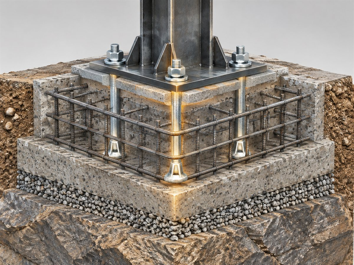
Quick answer
- Anchor bolts tie the supported structure to the foundation and resist tension, shear, or both.
- They resist uplift in tension and resist overturning by creating a tension-compression couple with the foundation.
- They resist sliding by adding shear capacity and by clamping the base plate to the concrete.
- They maintain preload and joint contact, which reduces rocking, micro-slip and fatigue.
- They help complete the load path from a concentrated column or equipment load into the concrete and reinforcement.
- In tie-down, rock-anchor and post-tensioned systems, they can transfer load to deeper, more competent ground.
- They do not increase the bearing capacity of the soil or the concrete. The footing, reinforcement, grout, plate and installation must still be adequate.
What "foundation stability" means at the anchor bolt
Foundation stability is not one check. It is a set of checks for bearing, settlement, sliding, overturning, uplift and, in some structures, dynamic or seismic response. Anchor bolts participate in only some of these. Knowing which ones prevents the common mistake of using a bolt to solve a soil or geometry problem.
| Stability issue | What the foundation must do | How anchor bolts contribute | What they do not fix |
|---|---|---|---|
| Bearing failure | Transfer compression to soil or rock without shear failure | Little direct effect; in anchored systems, load can be transferred deeper | Footing size, soil strength, weak layers |
| Settlement | Limit vertical deformation | Limited; deep anchors can reach a stiffer stratum | Compressible soil, voids, consolidation |
| Sliding | Resist horizontal translation | Shear through bolts, friction at the base, shear lugs | Insufficient passive resistance or friction |
| Overturning | Resist rigid-body rotation | Tension on one side and compression on the other form a resisting couple | Small footing, low dead load, weak soil |
| Uplift | Resist net vertical tension | Tie-down tension from cast-in, post-installed or post-tensioned anchors | Buoyancy or uplift larger than the anchor system |
| Cyclic or vibration | Maintain contact and limit movement | Preload and clamping reduce slip and wear | Resonance, fatigue, or a flexible plate |
The table is a map, not a design method. A foundation can be stable in bearing but fail in sliding. It can resist sliding but rock under cyclic load because the anchor bolts were never preloaded. Each mode needs its own check.
The load path: where the anchor bolt does its job
An anchor bolt is only as useful as the load path it completes. For a typical column base or machine foundation, that path runs:
- Supported structure — column, base plate, equipment frame or tower leg.
- Base plate and stiffeners — spread the load and bear on the grout.
- Grout pad — fills the gap and provides continuous bearing.
- Anchor bolt or rod — carries tension, shear or both.
- Concrete and reinforcement — resists bearing, breakout, splitting and bond.
- Soil or rock — carries the resulting foundation load.
The weakest link governs. A high-strength bolt embedded in a small, lightly reinforced concrete block can fail at a low load by concrete breakout. A large footing with a thin base plate can fail by plate bending before the anchor reaches its tensile capacity. A well-designed anchor in a grout pad with voids can lose stiffness and rock under load.
This is why anchor bolt selection cannot be separated from the base plate, grout, reinforcement and foundation geometry. The bolt is a component of a system, not a standalone product.
Six ways anchor bolts improve foundation stability
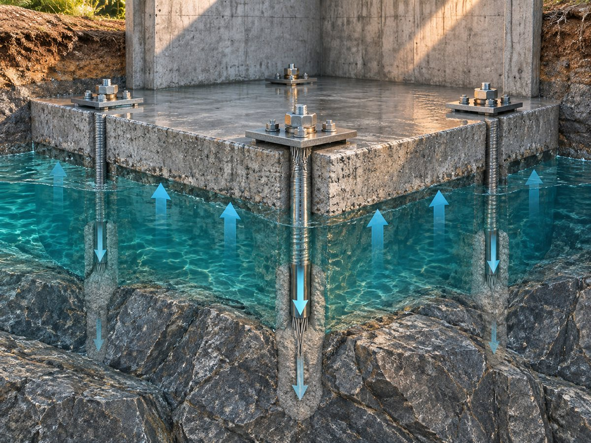
They resist uplift and tie the structure down
Uplift comes from wind, seismic action, hydrostatic pressure, equipment overturning moments, cable tension, or a tall, lightly loaded structure. The anchor bolts carry the net tension that the dead load cannot offset. The foundation must then resist the anchor force through concrete breakout, pullout, bond or supplementary reinforcement.
The important distinction is between the bolt's tensile strength and the anchor's tension capacity in the concrete. A bolt can be strong in tension and still fail at a low load if the embedment is shallow, the edge distance is small, or the concrete is cracked. The design capacity is the lowest of the steel, concrete and bond limit states, after the applicable factors.
They resist sliding and shear
Horizontal loads come from wind, seismic action, braking, thermal movement, earth pressure, or machine vibration. Anchor bolts resist sliding by carrying shear across the base, and by clamping the plate so that friction can develop. Some designs add a shear lug or a keyed joint because the anchor bolts alone are not an efficient shear path.
Shear in an anchor bolt is not only a steel check. The concrete can fail by edge breakout or pryout, especially when the anchor is close to a free edge or the plate is stiff enough to pry against the concrete. A bolt that is adequate in tension may be inadequate in shear at the same edge distance.
They control overturning and rocking
Overturning is a moment problem. On the tension side, the anchor bolts stretch and pull the foundation; on the compression side, the concrete and soil carry the bearing pressure. Together they form a resisting couple. The anchors reduce rotation only if they are embedded well enough to develop tension and if the base plate is stiff enough to distribute the compression.
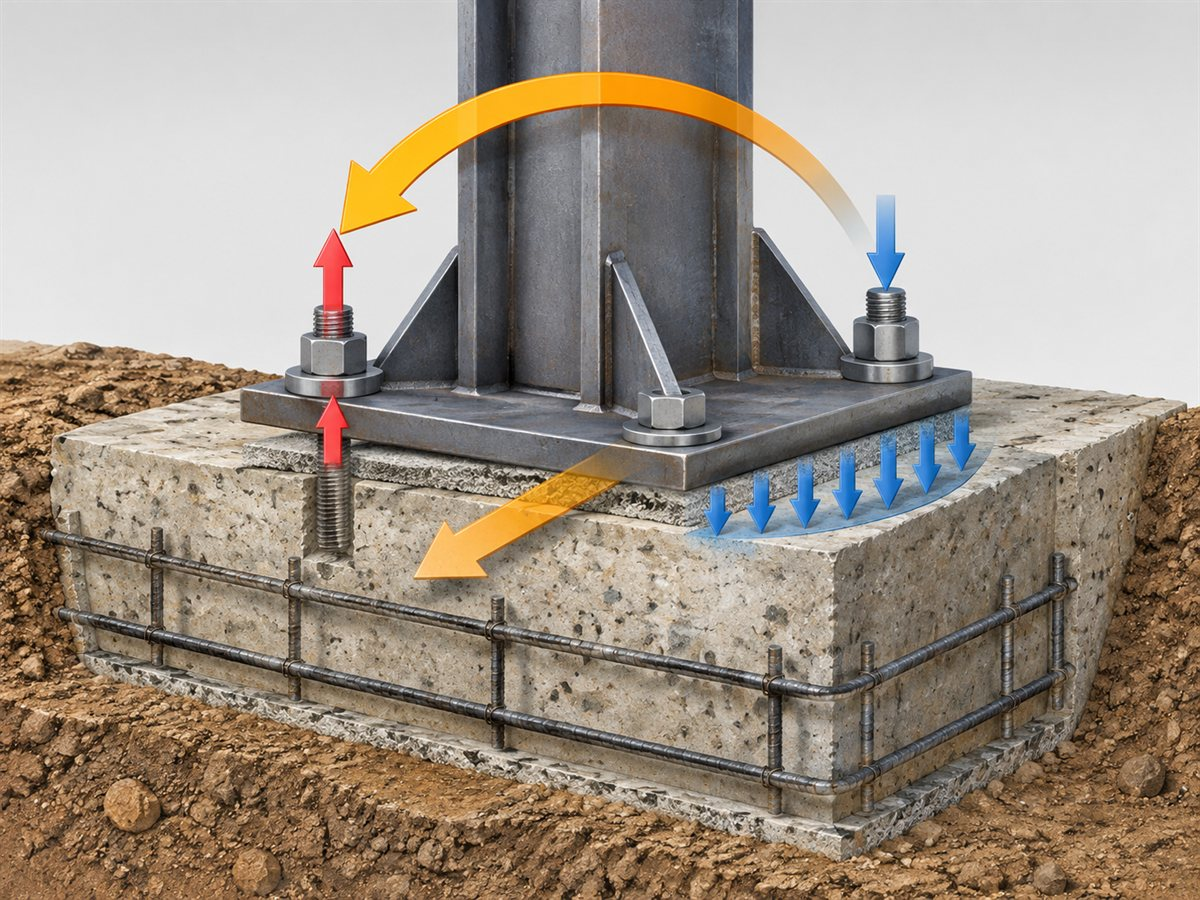
A flexible base plate can allow the column to rock even when the anchors are strong. The anchor elongation, plate deformation, grout compression and concrete strain all contribute to rotation. For equipment or structures with cyclic loads, that rotation can lead to fatigue at the anchor, nut or weld. Preload and a stiff, well-grouted base improve the behavior.
They maintain clamping force and composite action
A preloaded anchor bolt clamps the base plate to the grout and concrete. That clamping force closes gaps, reduces micro-slip, improves stiffness and helps the plate, grout and foundation act together. It also reduces the chance that the anchor is loaded in reverse tension under cyclic action.
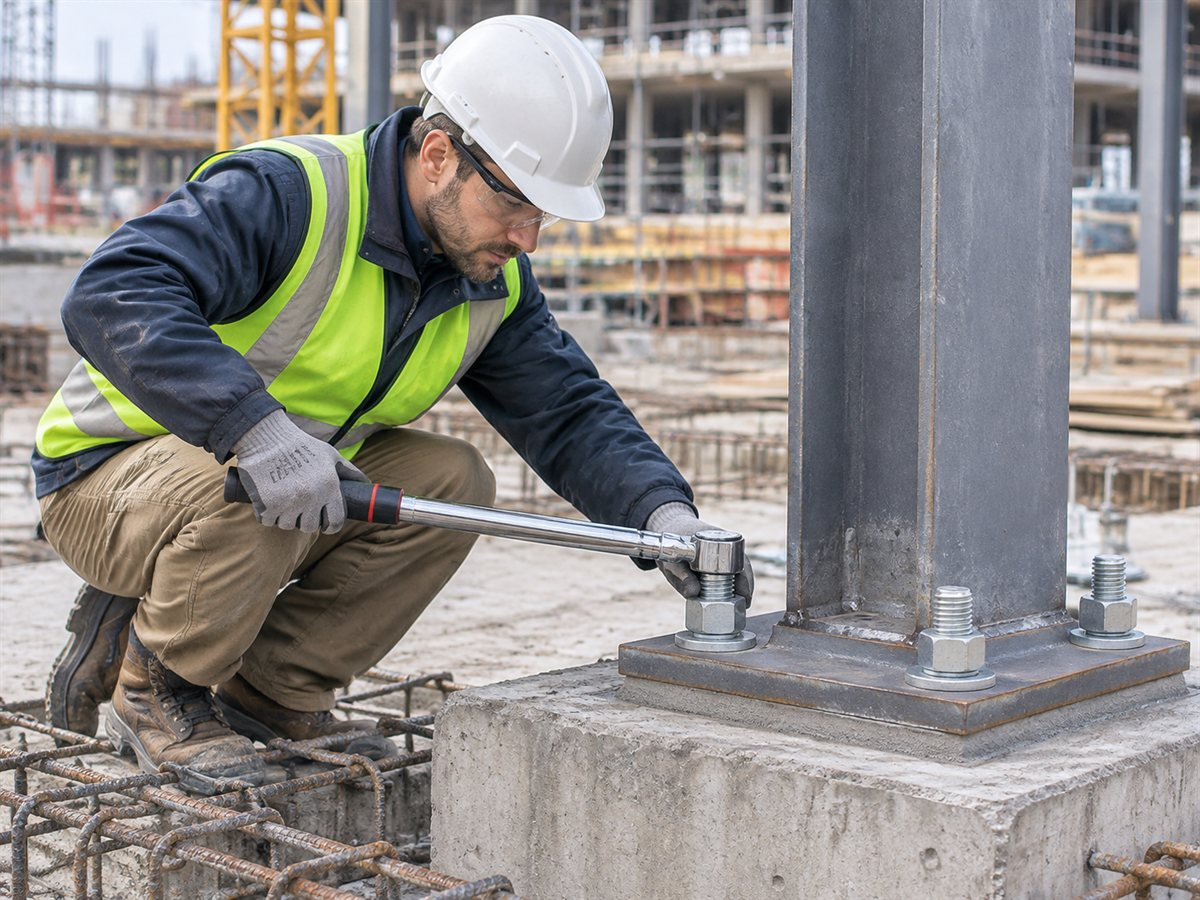
"Snug" is not the same as "preloaded." Torque is an indirect measure of tension and is affected by thread friction, lubrication, washer condition and nut geometry. For critical anchors, tensioning is measured directly or correlated with torque by calibration. The installation procedure should state the preload, the method and the tolerance.
They help distribute concentrated loads into the concrete
A column base or machine foot applies a concentrated load. The base plate spreads that load over a larger area; the grout fills the gap; the anchor bolts and embedded plates transfer tension and shear into the concrete; and the reinforcement distributes the resulting forces. If the plate is too thin, it bends and concentrates bearing at the edges. If the grout is voided, the plate bears on a few high points. If the anchor is headed, the head spreads the tension into a larger concrete area; if it is a straight threaded rod, the bond or the nut and plate must do that job.
Supplementary reinforcement can improve ductility and control cracking, but it does not replace the anchor design. The failure mode can shift from concrete breakout to steel yielding, which may be preferable, but only if the detailing and anchorage are correct.
They transfer load to deeper, competent ground
Some foundation problems cannot be solved at the surface. The upper soil may be soft, loose or compressible; the rock may be weathered; the structure may be subjected to uplift or lateral load that the shallow footing cannot resist. In these cases, a tie-down, rock anchor, anchor cable or grouted bar can transfer load to a deeper, stiffer stratum.
This is the sense in which an anchor system can improve overall foundation stability rather than only the connection. The anchor must reach ground that can carry the load, and the bond length, free length, anchor head and corrosion protection must be designed as a system. A long anchor that stops in the weak zone adds little. A short anchor that reaches competent ground can do more than a longer one that does not.
Global stability is a separate check. The anchor bond zone must sit beyond the critical failure surface, and the anchor force must be included in the stability analysis. An anchor that is strong but too short to pass the slip surface can pull the whole wedge with it.
The same principle applies to rock bolts and ground anchors in mining and civil works: the steel is only useful if the load can pass into a competent medium. CQ Rockbolt's anchor cable, PT bar and grouting product pages describe systems for that kind of load transfer.
Cast-in, post-installed and post-tensioned anchors
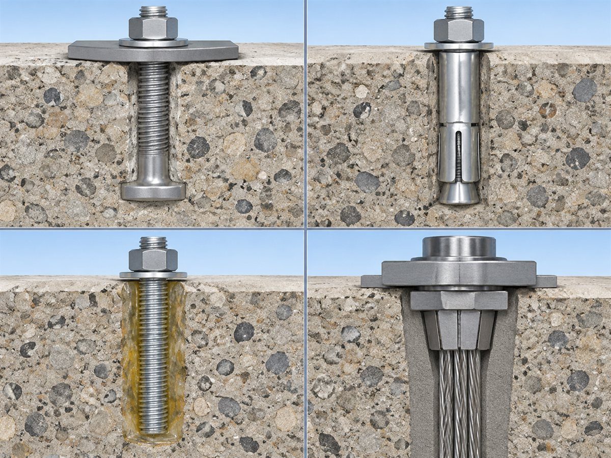
There are four common anchor types used in concrete foundations. They are not interchangeable, and the choice affects the design, the installation procedure and the inspection plan.
| Type | How load is transferred | Best fit | Critical checks | Main limitation |
|---|---|---|---|---|
| Cast-in headed or bent bolt | Bearing at the head or bend, bond along the embedment | New foundations, heavy uplift, vibration, seismic | Embedment, template position, consolidation, edge distance | Requires accurate setting before concrete placement |
| Post-installed mechanical anchor | Friction, expansion, wedge or undercut | Retrofit, existing concrete, moderate loads | Hole diameter, cleaning, torque, edge distance, cracked concrete | Sensitive to installation quality; qualified product required |
| Post-installed adhesive anchor | Bond between steel, adhesive and concrete | Close spacing, cracked concrete, retrofit, variable geometry | Hole cleaning, moisture, temperature, cure, annulus | Cure time and hole condition govern; not a gap filler |
| Post-tensioned bar or strand | Mechanical anchorage and tensioning against a plate | High uplift, tie-downs, deep foundations, strengthening | Anchor head, wedge, coupler, tensioning, grout, corrosion | Requires tensioning equipment and records |
Cast-in anchor bolts: the default for heavy foundations
Cast-in anchors are placed before the concrete is poured. A headed bolt develops tension through a bearing head at the embedded end. A J-bolt or L-bolt develops tension through the bend and the bond along the embedment. Headed anchors are generally more predictable for high tension because the load is transferred by bearing rather than relying only on bond.
The critical checks are template position, embedment depth, verticality, projection length, thread protection and concrete consolidation. A bolt that is set too close to an edge, or that is displaced during pouring, may not be correctable later. Voids under the head or around the embedment reduce capacity. The thread must be protected from concrete and damage until the nut is installed.
Post-installed mechanical anchors: retrofit and existing concrete
Mechanical anchors are installed in a drilled hole and develop load by expansion, wedging, undercutting or friction. They are common in retrofits, equipment replacement and foundations where cast-in bolts were omitted or misplaced. Their performance depends on the hole diameter, hole cleaning, drilling method, embedment, edge distance, concrete strength and the presence of cracks.
Where ACI 318 governs, post-installed mechanical anchors should be qualified to ACI 355.2 for the intended application. The qualification category matters: an anchor qualified only for uncracked concrete is not automatically suitable for a cracked section, and an anchor qualified for static loads is not automatically qualified for seismic or fatigue. The installer must follow the manufacturer's hole size, cleaning and torque procedure.
Adhesive anchors: bond-dependent
Adhesive anchors use a chemical adhesive to bond a threaded rod or bar to the concrete. They can be useful where close spacing, small edge distance or variable hole geometry makes a mechanical anchor difficult. The bond is sensitive to hole cleaning, moisture, temperature, hole roughness, annulus and cure time.
Where ACI 318 governs, adhesive anchors should be qualified to ACI 355.4 for the intended application. The installation procedure must include the correct drill bit, hole depth, cleaning method, adhesive volume, mixing, insertion and cure time. A dusty or wet hole can reduce bond dramatically. The adhesive is not a substitute for a properly sized and embedded anchor.
Post-tensioned bars and strand anchors: preload and deep tie-down
A post-tensioned anchor is tensioned after installation and locked against a bearing plate. PT bars are threaded high-strength bars; strand anchors use multi-wire strand and a wedge-type anchorage. They are used for high uplift, tie-downs, foundation strengthening, rock anchors and deep foundations.
The design must define the anchor head, bearing plate, wedge or nut, coupler, free length, bond length, grout and corrosion protection. Tensioning must be done in stages, with elongation and load recorded. The exposed strand should be cut with a suitable cold-cutting method, not a method that damages the strand or the anchorage.
Post-tensioning also compresses the concrete or rock against the bearing plate. That compression can improve crack control and stiffness, but it must be designed; over-tensioning can crack the concrete or overload the anchorage.
The limit state that actually governs
Anchor design is not a single strength calculation. It is a set of checks, and the lowest result governs. The main limit states are:
| Limit state | What happens | Main controls |
|---|---|---|
| Steel tension | Bolt, thread or nut yields or fractures | Diameter, grade, thread, net area, nut engagement |
| Concrete breakout in tension | A cone of concrete pulls out | Embedment, edge distance, spacing, concrete strength, cracking |
| Pullout | The anchor pulls out of the concrete | Anchor type, head or expansion mechanism, embedment |
| Side-face blowout | Concrete spalls at the side of a deeply embedded anchor | Edge distance, cover, bar spacing |
| Steel shear | Bolt yields or fractures in shear | Diameter, grade, shear plane |
| Concrete edge breakout in shear | Concrete breaks toward a free edge | Edge distance, load direction, member thickness |
| Pryout | Concrete is pried out opposite the load | Anchor stiffness, embedment, edge distance |
| Bond failure | Adhesive or grout bond fails | Hole cleaning, moisture, bond length, adhesive type |
| Plate or weld failure | Base plate bends, weld cracks, nut pulls through | Plate thickness, stiffeners, weld size, washer |
| Corrosion or fatigue | Section loss or progressive cracking | Coating, environment, stress range, detailing |
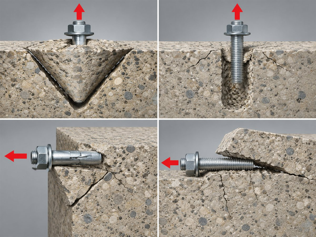
A catalog tensile strength is not an anchor capacity. It is a property of the steel. The design capacity is the lowest factored resistance among the steel, concrete and bond limit states. That is why two anchors with the same diameter can have very different capacities in a foundation.
Cracked concrete deserves special attention. In a foundation, cracks can occur from shrinkage, flexure, settlement or seismic action. An anchor qualified only for uncracked concrete may have a much lower capacity in a cracked section. The design should state whether the concrete is assumed cracked or uncracked, and the product qualification should match that assumption.
Outside the ACI system, EN 1992-4 provides a comparable European framework for fastenings in concrete. The terminology and factors differ, but the governing questions are the same: what load goes into the anchor, what concrete or bond resistance is available, and which failure mode is acceptable.
Installation and inspection: where good design is lost
Many anchor failures are not caused by a missing calculation. They are caused by a detail that was not installed as designed. The following checks should be part of the inspection plan.
Before concrete placement
- Confirm the anchor template against the base plate drawing.
- Check embedment depth, projection length, verticality and edge distance.
- Confirm the anchor type and head or bend geometry.
- Check that the anchor is tied to the reinforcement so it cannot move during pouring.
- Protect the thread with caps or tape.
- Confirm that the anchor does not clash with reinforcement or embedded items.
During concrete placement
- Consolidate the concrete around the anchor; avoid voids under the head or plate.
- Check the anchor position after vibration.
- Confirm the concrete strength and curing match the design assumption.
- Record any displacement or repair.
For post-installed anchors
- Scan for reinforcement before drilling.
- Use the specified drill bit and hole depth.
- Clean the hole with the specified brush and blowing procedure.
- Check hole diameter and condition.
- Follow the adhesive or mechanical anchor installation instructions exactly.
- Respect cure time, temperature and moisture limits.
- Torque or tension to the specified value with a calibrated tool.
For grouted and post-tensioned anchors
- Confirm the grout mix, temperature and pressure.
- Check that the grout fills the annulus and the bond length.
- Confirm the anchor head, wedge or nut is seated correctly.
- Tension in stages and record load and elongation.
- Seal the anchor head against corrosion.
Inspection and testing
- Verify the as-built anchor layout, embedment and projection.
- Check the nut, washer and plate seating.
- Confirm the grout pad is full and sound.
- Conduct pull tests on a sample of anchors where the project requires it.
- Record the test load, displacement, failure mode and location.
- Compare the results with the specified acceptance criteria.
A pull test is a sample check, not a proof that every anchor is correct. The test load and acceptance criteria must be defined by the project design. ASTM E488 provides standard test methods for anchors in concrete, but it does not set the acceptance criteria for a particular project.
Common mistakes that make anchor bolts ineffective
- Treating the catalog tensile strength as the foundation capacity. The concrete, bond and plate may govern at a much lower load.
- Ignoring edge distance. A strong anchor close to a free edge can fail by concrete breakout.
- Using a short embedment. A long bolt that is not embedded deeply enough does not develop its capacity.
- Assuming a J-bolt is equivalent to a headed anchor. The bend and bond must be designed and detailed.
- Using an uncracked-concrete anchor in a cracked section. The qualification category matters.
- Poor hole cleaning in a post-installed anchor. Dust, water or debris can reduce bond or expansion.
- Over-torquing or under-torquing. Torque is not tension; use the specified method and calibration.
- Grout voids or soft shims. The base plate must bear continuously; point bearing causes bending and rocking.
- Mixing metals without considering corrosion. Galvanic coupling and coating damage can shorten the service life.
- Using anchor bolts to fix a soil or footing problem. Anchors transfer load; they do not increase bearing capacity.
- Skipping as-built checks. A misplaced anchor can force a field modification that changes the load path.
RFQ and specification checklist
A useful quotation starts with a complete load path, not only a bolt diameter. Send the following information to the supplier and ask for the exact product datasheet, not a generic catalog page.
| Item | What to state | Why it matters |
|---|---|---|
| Foundation drawing | Plan, section, base plate, anchor layout | Defines edge distance, spacing, embedment and projection |
| Loads | Tension, shear, moment, uplift, fatigue, seismic | Selects the anchor type and capacity |
| Concrete | Strength, age, cracked/uncracked, reinforcement | Controls breakout, bond and splitting |
| Anchor type | Cast-in, mechanical, adhesive, post-tensioned | Different design and installation rules |
| Product | Diameter, grade, thread, length, coating | Defines steel capacity and corrosion resistance |
| Geometry | Embedment, edge distance, spacing, plate size | Governs concrete limit states |
| Grout | Type, thickness, strength, placement method | Affects bearing and load transfer |
| Environment | Indoor, outdoor, marine, chemical, temperature | Selects coating and material |
| Testing | Pull test, tensioning record, MTC, test standard | Defines acceptance evidence |
| Installation | Access, drilling method, torque/tension equipment | Confirms the design can be installed |
| Commercial | Quantity, destination, required date, marking | Makes the quotation comparable |
Ask the supplier to confirm:
- the exact standard and grade of the bar or strand;
- the anchor type and qualification category;
- the recommended hole diameter and depth;
- the installation torque or tension;
- the grout or adhesive requirements;
- the corrosion protection and expected service life;
- the test reports and traceability documents;
- the accessories included: nut, washer, plate, wedge, coupler, grout tube.
How CQ Rockbolt products fit foundation anchoring
CQ Rockbolt's public catalog includes products that can be used in foundation, tie-down and anchorage work. The values below are published catalog data; the project design, exact grade and datasheet govern.
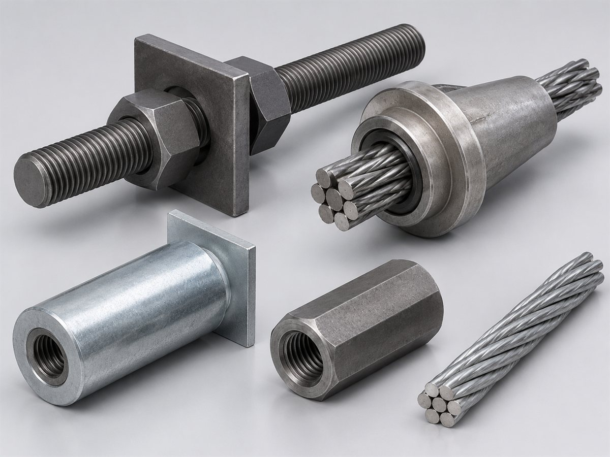
PT bars and prestressing thread bars. CQ's public PT bar page describes a 12–40 mm range and highlights 25 mm, 32 mm and 40 mm as common sizes. It also states a yield strength up to 830 MPa and, separately, a tensile range of 1860–2000 MPa, with ASTM A722 and GB/T 5224 references. These bars can be supplied with nuts, couplers and anchor plates for post-tensioned and foundation applications. Confirm the exact grade, diameter, thread and coating for the project.
Prestressing anchorage systems. CQ's prestressing anchorage page lists single-hole and multi-hole anchorages, wedge-type and threaded anchorages, anchor plates, wedges and couplers. The page states a working load up to 2,600 kN depending on configuration and an anchorage efficiency of at least 95%. These are catalog values; the anchorage must be matched to the bar or strand and supported by the project's test and documentation requirements.
Single-hole anchors. CQ's single-hole anchor page lists the YM12-1, YM15-1 and YM17-1 models with published rated anchoring forces of 150 kN, 190 kN and 240 kN, and describes use in foundation-pit anti-floating, basement anti-floating and small anchor bolts. The rated force is not the design capacity; confirm the strand size, anchor head, corrosion protection and safety factors.
Steel strand anchor cables. CQ's steel strand anchor cable page lists 1×7 strand including 15.2 mm, 17.8 mm and 21.6 mm diameters, a 1860 MPa grade and minimum breaking loads of 260 kN, 353 kN and 530 kN. These are strand properties, not installed system capacities. For foundation tie-downs, confirm the bond length, free length, anchorage, grout and corrosion system.
Resin capsules and anchorage agents. CQ's resin capsule page lists a two-component system, bore diameters of 28–45 mm, compressive strength of at least 60 MPa, typical tensile strength of at least 15 MPa, fast/medium/slow curing, a working temperature of -10°C to 40°C and a shelf life of 6–12 months. These are catalog values. For a post-installed anchor in concrete, confirm the adhesive is qualified for the application and follow the hole-cleaning and cure requirements.
Self-drilling hollow grouting bolts. CQ's self-drilling hollow grouting rock bolt page describes a hollow threaded bar that combines drilling, grouting and anchoring, and lists foundation reinforcement and pile foundation underpinning among its applications.The grout flows through the bar to the hole bottom, which can be useful in weak or collapsing ground. Confirm the bar diameter, length, drill bit, grout pressure and corrosion protection for the foundation condition.
Plates, nuts and washers. CQ also lists dome plates and anchor plates, spherical washers, hex nuts, dome nuts and flanged nuts. The plate and nut are part of the load path; they must match the anchor diameter, thread, bearing area and design load.
To review a foundation anchoring system, send:
- the foundation and base plate drawings;
- the design tension, shear, moment and uplift;
- the concrete strength and cracked/uncracked assumption;
- the anchor layout, edge distance and spacing;
- the required embedment and projection;
- the grout, corrosion and fire requirements;
- the test and documentation requirements;
- the quantity, destination and required date.
Contact CQ Rockbolt with the project details. The team can then confirm the exact bar, anchorage, plate, accessory and available documentation for the quotation.
Conclusion
Concrete anchor bolts improve foundation stability by completing the load path between the structure and the foundation. They resist uplift, shear and overturning; maintain clamping force; help distribute concentrated loads; and, in tie-down and deep-anchor systems, transfer load to competent ground.
They do not replace an adequate footing, reinforcement, grout or installation procedure. The anchor capacity is governed by the weakest link—steel, concrete, bond, plate or grout—and the installation must be inspected as carefully as the design is calculated. When those conditions are met, anchor bolts turn a foundation from a concrete block into a controlled structural system.
Related News
Other news you might be interested in

Self-Drilling Anchor Bolts for Water-Conveyance Tunnel Reinforcement
Self-drilling anchor bolts are useful for water-conveyance tunnel reinforcement when broken or water-bearing ground makes conventional drill-and-insert bolting difficult. By using a hollow threaded bar as both the drilling member and the permanent reinforcement, the system removes the separate bolt-insertion step and provides a channel for grouting through the same bar.For a water-conveyance tunnel, that installation advantage matters. Headrace, tailrace, diversion, irrigation and water-supply tunnels can pass through fault zones, weathered rock, weak interlayers and interconnected fractures. Groundwater may enter the excavation, boreholes may deteriorate after drilling, and support must be coordinated with drainage, waterproofing and the final lining.

What Is a Split Set Mining System and How Is It Different from Other Rock Bolts?
A split set is often described as a rock bolt, but in mining it is more useful to think of it as a support system. The steel tube is the most visible part. The way it performs also depends on the drilled hole, the bearing plate, the installation adapter, the drilling equipment, the surface support and the checks made underground. That distinction matters when a project compares rock bolts. Two quotations can list a similar diameter and length, yet propose different load-transfer mechanisms, different hole requirements and different installation procedures. A split set is not a resin bolt with the resin removed. It is not a mechanical expansion-shell bolt, a self-drilling hollow bar, a water-inflatable tube or a cable bolt. Each product family solves a different part of the ground-support problem.
Want to know more?
Get in touch with us for more information about our services and products.