

Self-Drilling Anchor Bolts for Water-Conveyance Tunnel Reinforcement

Dayang Yang
AuthorWith over 15 years of experience in the production and sales of ground anchoring and mining support products, we operate our own rock bolt and accessory manufacturing facility with stable large-scale production capacity. We are specialists in rock bolts, resin cartridges, anchor cables, bearing plates, and customized ground anchoring products for mining support and geotechnical anchoring solutions.
Self-drilling anchor bolts are useful for water-conveyance tunnel reinforcement when broken or water-bearing ground makes conventional drill-and-insert bolting difficult. By using a hollow threaded bar as both the drilling member and the permanent reinforcement, the system removes the separate bolt-insertion step and provides a channel for grouting through the same bar.
For a water-conveyance tunnel, that installation advantage matters. Headrace, tailrace, diversion, irrigation and water-supply tunnels can pass through fault zones, weathered rock, weak interlayers and interconnected fractures. Groundwater may enter the excavation, boreholes may deteriorate after drilling, and support must be coordinated with drainage, waterproofing and the final lining.
A successful reinforcement system therefore needs more than a strong steel bar. It needs a bar that reaches the specified depth, compatible components, controlled grouting and a durability detail suited to the water environment. This article explains where self-drilling anchor bolts fit in that system and how CQ Rockbolt’s published product range can support project selection.
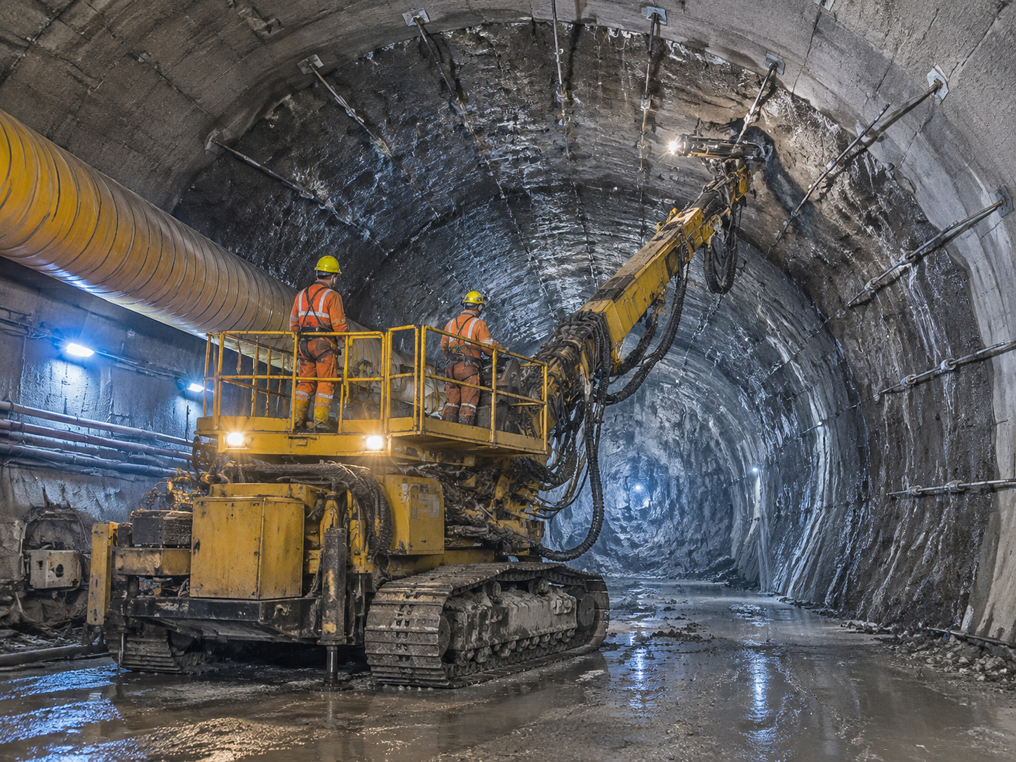
Why Water-Conveyance Tunnels Need Reliable Rock Reinforcement
Excavation changes the stress conditions around a tunnel. In jointed or weak rock, blocks can loosen, bedding planes can separate, and the crown or sidewalls can deform before the final lining is installed.
Water adds another variable. Flow through fractures can carry fines, soften susceptible rock and interfere with grout placement. These conditions can change over a short distance, so a support method that works in one reach may become difficult to install in the next.
The reinforcement has several connected duties:
- Restrain loose blocks and limit separation around the opening.
- Transfer load between the rock and the support elements.
- Help maintain the excavation profile during construction.
- Provide stable conditions for the lining sequence.
- Remain suitable for the specified service life and groundwater exposure.
Rock bolts work with other measures, including shotcrete, mesh, steel arches, drainage and ground treatment. The design must also consider whether the tunnel will remain unlined, receive a concrete lining or use a steel liner. Each arrangement has different requirements for water pressure, leakage and the interface between the support and the finished tunnel.
The Installation Problem in Broken, Wet Ground
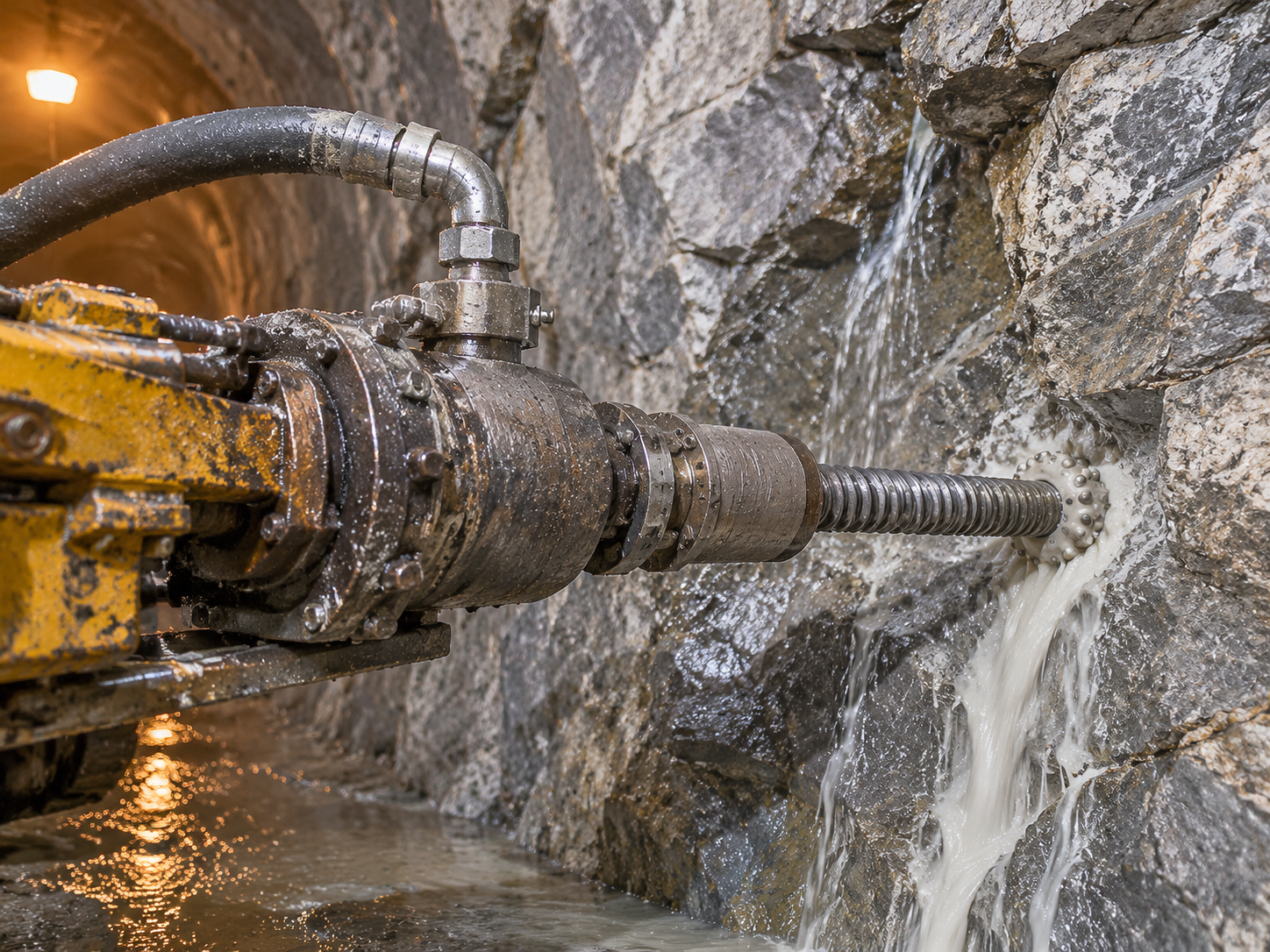
A conventional grouted bolt normally requires the crew to drill a hole, withdraw the drill string, insert the bolt and complete the grouting. This sequence is effective where the borehole remains stable.
In fractured or water-bearing ground, the interval between drilling and insertion can become the weak point.
Loose fragments may fall into the hole after the drill string is removed. Soft material can close around the opening. A block can obstruct the bolt, preventing it from reaching the design depth. Water can continue entering through connected joints while grout escapes into fractures or is washed away before it sets.
The consequences extend beyond slower installation. A bolt can appear complete at the collar while its embedment or grout bond is shorter than intended. Once shotcrete or concrete covers the support, identifying and correcting that defect becomes more difficult.
Self-drilling anchor bolts address the separate insertion problem by keeping the reinforcing bar in position throughout drilling. This can reduce failed holes and repeated handling where a conventional open hole is unreliable.
Water control still needs separate attention. Leaving the bar in the hole does not, by itself, prevent grout loss or make an uncontrolled inflow suitable for injection.
How the Self-Drilling Anchor System Works
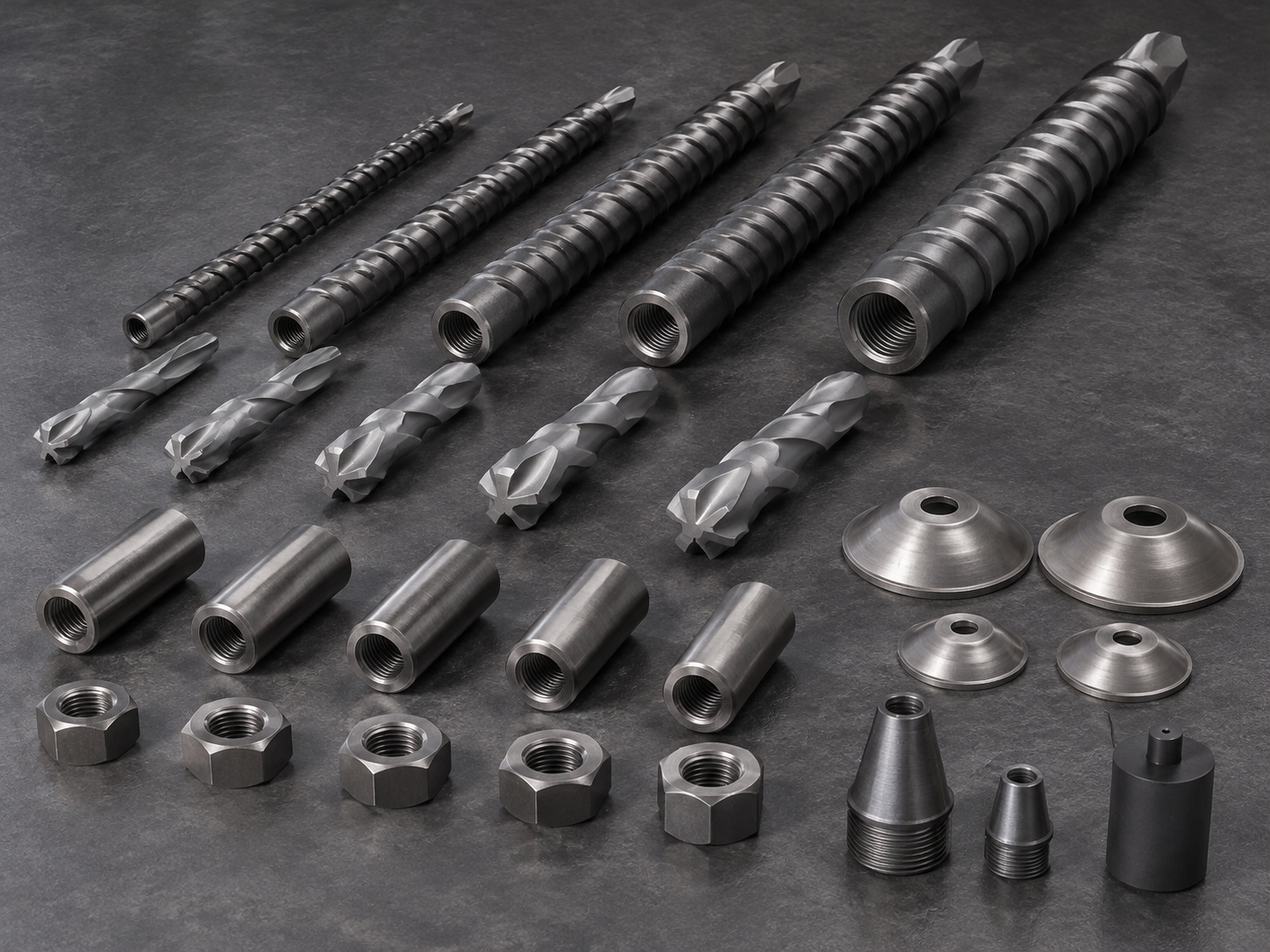
A self-drilling anchor bolt consists of several matched components:
| Component | Function in the system |
|---|---|
| Hollow threaded bar | Transmits drilling forces, carries grout and remains as reinforcement |
| Sacrificial drill bit | Forms the hole and remains at the end of the installed bar |
| Coupler | Connects bar sections where the required length exceeds the available section or rig feed |
| Grout adapter or injection head | Connects the injection equipment to the hollow bar |
| Collar stopper or packer, where specified | Controls sealing or staged injection according to the grouting method |
| Bearing plate and nut | Transfer load at the exposed rock surface and support the specified head detail |
During installation, the bit drills the hole while the hollow bar advances into the ground. Couplers are added as required. Grout travels through the internal bore and exits near the bit, allowing the annular space around the bar to be filled from the far end toward the collar.
Some systems allow simultaneous drilling and grouting; others are drilled first and grouted afterward. CQ Rockbolt’s self-drilling hollow grouting rock bolt page describes simultaneous drilling and grouting as a system capability. The actual sequence, flushing medium, grout and return criteria must follow the approved method for the equipment and ground.
The installed load path includes the steel bar, threaded connections, grout and surrounding rock. The bearing plate and nut complete the surface detail. Where pre-tension is specified, it should be applied only after the anchorage has reached the strength required by the approved procedure.
The general sequence is covered in CQ Rockbolt’s guide to installing self-drilling rock bolts in tunnels.
Where Self-Drilling Anchor Bolts Fit in Water-Conveyance Tunnels
Portals and Shallow-Cover Sections
Tunnel portals often combine weathered ground, limited cover, surface water and restricted working space. Boreholes may ravel or close before a separate bolt can be inserted.
A self-drilling system allows the reinforcement to advance with the drilling operation. Shorter bar sections and couplers can also help where the rig feed or available headroom limits handling.
Shallow cover requires particular care with injection pressure. Grout can break through to the surface, lift the ground or escape along a slope. Pressure limits must reflect the available confinement, with monitoring and staged injection where specified. The product catalog’s general pressure guidance should not be adopted as a portal setting.
Where the material is residual soil rather than rock, the reinforcement needs the corresponding soil-nail, bond, facing and corrosion design checks.
Fault Zones and Crushed Rock
Fault zones can contain crushed rock, clay gouge, intact lenses and flowing fractures within the same excavation face. The ground may stand briefly during drilling and then deteriorate.
Keeping the bar in position can make self-drilling anchors easier to install under these conditions. However, the bond still needs verification. Drilling can smear or remold clay gouge, and open fractures can take grout without leaving a continuous annulus.
Trials should therefore confirm the bit, flushing or grouting method and installed bond in representative ground. Where grout loss or poor bond remains uncontrolled, additional ground treatment or a different support measure may be necessary.
Crown and Sidewall Reinforcement
In blocky or bedded rock, the crown and sidewalls may need reinforcement soon after excavation. Overhead access and long-bar handling can make a separate insertion step difficult.
Self-drilling bolts reduce that handling by leaving the drilled bar in place. The head arrangement can be coordinated with mesh, straps, steel arches and shotcrete to restrain smaller fragments and distribute surface loads.
The bolt angle, length, spacing and plate arrangement must come from the support design. A strong bar alone cannot compensate for an unsuitable support pattern.
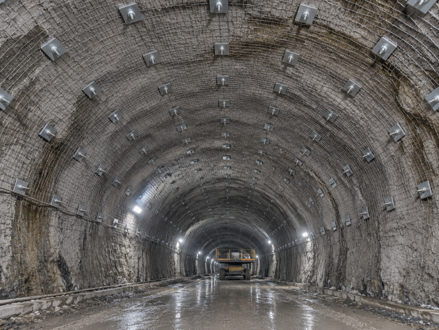
Face and Advance Support
Where the face is unstable, self-drilling elements may be considered for reinforcement ahead of excavation. Their suitability depends on the required length, installation angle, overlap, rig reach and grouting arrangement.
Advance support is a separate design case from radial bolting around the tunnel perimeter. It should be detailed with the excavation sequence and other support measures rather than adopted from a standard radial bolt pattern.
Rehabilitation and Re-Support
Existing water tunnels can present wet rock, deteriorated support, restricted clearance and a lining that must be protected during drilling.
Self-drilling installation can be useful where the exposed ground will not hold an open hole. Before adding reinforcement, the rehabilitation design should assess the existing lining and support, locate embedded services or reinforcement, and define how any penetration will be sealed and protected.
Water-Specific Controls That Determine Performance
Characterize the Water Before Selecting the Grout
“Wet ground” is too broad a description for selecting a grouting method. The project should distinguish between residual drilling water, slow seepage, flowing fractures and pressurized inflow.
Useful information includes:
- Inflow location, rate and pressure.
- Whether the water carries fines.
- Seasonal changes or changes associated with reservoir operation.
- Groundwater chemistry and its relevance to steel, coatings and grout.
- Whether the rock softens, slakes or closes after drilling.
A stable hole containing residual flushing water is different from a fracture that continuously carries grout away. The second condition may require water-control measures, staged injection or another treatment before the anchor can be accepted.
Control Grout Placement and Injection Pressure
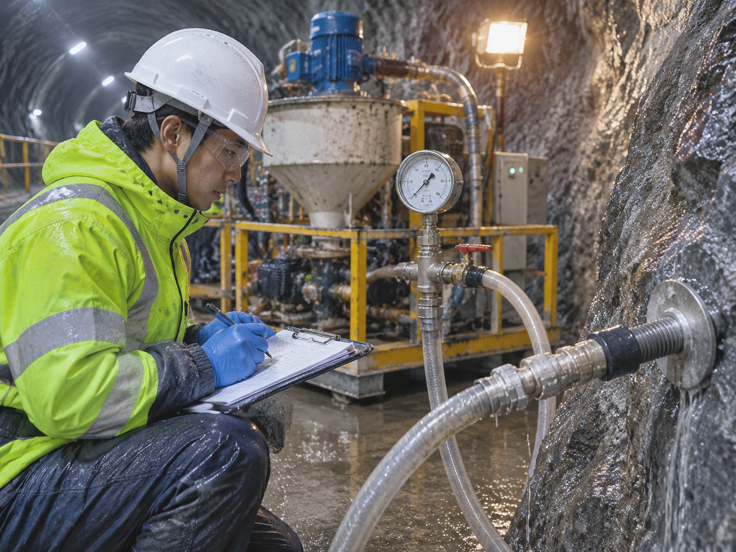
Grout must develop the specified bond while remaining placeable under the actual water conditions. Mix stability, bleeding, setting time and resistance to washout can matter as much as compressive strength.
Any additives must be compatible with the grout and approved for the intended service. Trial work should establish the procedure rather than using additives to force grout into an uncontrolled loss zone.
CQ Rockbolt publishes conventional grouting-pressure guidance of 0.5–2.0 MPa, with adjustment according to the rock, grout and design requirements. This is catalog guidance. The project must establish its own injection limits based on cover, confining stress, fractures, groundwater and nearby lining or waterproofing.
Pump pressure also includes line losses and elevation effects. The procedure should define where pressure is measured and how it relates to the injection point.
During production, record the grout batch, mix, pressure, volume, return and any interruption. If grout also serves as drilling flush, cuttings can contaminate the return; sampling and final grouting criteria should account for this.
Check the Annulus and Required Grout Cover
The nominal bar diameter is different from the hole diameter. The selected bit determines the nominal hole size, while the space around the bar forms the grout annulus.
For a centered bar in a nominal circular hole:
Nominal radial grout cover = (bit diameter − bar diameter) / 2
For example, a 25 mm bar with a 32 mm bit gives 3.5 mm of nominal radial space before thread geometry, drilling tolerance, eccentricity and ground irregularity are considered. That calculation describes geometry; it does not establish an acceptable permanent-corrosion detail.
The designer must confirm the required bond and minimum cover. A larger bit increases grout demand, while a small annulus may be unsuitable for the specified protection or placement method. Catalog compatibility alone does not establish suitability for permanent exposure to aggressive water.
Specify Durability for the Intended Service Life
A bolt left behind the final lining may become inaccessible. Its durability therefore needs to be considered before installation.
The specification should address the steel, coating or protection system, grout cover, groundwater chemistry and treatment of the exposed head. Accessible heads and fully embedded bolts may require different inspection provisions.
CQ Rockbolt describes its self-drilling bar as high-strength alloy structural steel with an anti-rust surface treatment. For permanent water-tunnel support, buyers should request the exact protection specification rather than treating “anti-rust” as a complete durability designation.
Initial support that is intended to remain as part of the permanent works should be specified and documented for that role from the outset.
Coordinate Reinforcement With the Hydraulic Design
Rock reinforcement, seepage treatment and the water-retaining structure perform related functions, but each needs its own design basis.
In an unlined or shotcrete-lined pressure tunnel, the rock mass may form part of the water-retaining envelope. The design must consider confinement, permeability, leakage and hydraulic jacking—the opening of rock joints when water pressure overcomes confinement.
In a concrete-lined tunnel, pressure resistance depends on the lining, surrounding rock and provisions assumed by the design. In a steel-lined section, the steel liner provides the water barrier, while load sharing with the surrounding concrete and rock depends on the specified interaction.
Steady and transient internal pressure, external groundwater pressure, and dewatering conditions must all be considered. Installing anchor bolts does not establish that a tunnel is suitable for its operating pressure.
Protect the Lining and Waterproofing Interface
The bolt head, plate and projection must fit the final lining detail. They should not damage a membrane, obstruct drainage or interfere with a steel liner and its backfill.
Any penetration through an existing lining needs a designed sealing and corrosion-protection detail. Where heads remain exposed to flow, they must meet the specified hydraulic profile.
CQ’s product page includes water-conveyance tunnel reinforcement and anti-seepage treatment among its applications. Grouting around an anchor can fill the annulus and some connected fractures, subject to ground conditions. It does not establish a tunnel-wide leakage barrier or replace curtain grouting, drainage, waterproofing or lining requirements.
CQ Rockbolt’s Published Self-Drilling Anchor Range
CQ Rockbolt lists R25, R32, R38, R51 and T76 self-drilling hollow grouting bars. The published specifications provide a starting point for discussing the required configuration.
| Model | Nominal Diameter (mm) | Inner Diameter (mm) | Tensile Strength (MPa) | Yield Strength (MPa) | Standard Length (m) | Matching Bit Diameter (mm) |
|---|---|---|---|---|---|---|
| R25 | 25 | 13 | ≥550 | ≥350 | 2 / 3 / 4 | 32 / 38 / 42 |
| R32 | 32 | 17 | ≥550 | ≥350 | 2 / 3 / 4 / 6 | 42 / 45 / 51 |
| R38 | 38 | 21 | ≥550 | ≥350 | 3 / 4 / 6 | 51 / 57 / 64 |
| R51 | 51 | 28 | ≥550 | ≥350 | 3 / 4 / 6 | 64 / 76 / 89 |
| T76 | 76 | 42 | ≥550 | ≥350 | 3 / 4 / 6 | 89 / 102 / 114 |
These are published catalog values. Confirm the exact bar, components, protection system and supporting documents for the ordered configuration.
The MPa values describe material strength. They are not the installed anchor capacity, which also depends on section geometry, connections, grout, bond length, rock and the head arrangement.
Selection should begin with the required support load and bond, then consider the bore, available equipment, handling and durability detail. A larger bar may require a larger bit, consume more grout and increase handling demands without resolving the actual installation problem.
CQ also lists matching bits, coupling sleeves, grout stoppers, plates and nuts. Its product page states that coupling sleeves can provide connection strength no less than the bar body. For procurement, confirm the exact coupler, engagement procedure and available assembly-test evidence for the selected size.
The surface-support arrangement can also include CQ’s dome plates and anchor plates and wire mesh, where specified by the tunnel design.
Installation Quality and Acceptance
The benefit of self-drilling installation depends on completing the designed anchor. A bar drilled to position is only one stage of that work.
Before production, a trial in representative ground should confirm the component combination, drilling method, grout take and acceptance procedure. During installation, give each hole an identifier and link it to the material and grouting records.
| Control Point | What to Check |
|---|---|
| Before drilling | Correct bar, bit, coupler, grout, rig interface and current support drawing |
| During drilling | Position, alignment, depth, coupler assembly and changes in water or ground |
| During grouting | Mix, pressure, volume, return condition, interruptions and signs of loss |
| At the head | Plate seating, nut arrangement, specified tensioning stage and protection |
| Before lining | Projection, recess, coating repair, membrane clearance and sealing detail |
| During testing | Test configuration, grout age, load, hold time, displacement and required acceptance criteria |
Representative or sacrificial test anchors can help assess bond in the actual ground. Where the test location differs from production conditions, record and justify the difference.
Test results should be interpreted according to what was tested. Bar/grout pull-out, grout/rock failure, rock failure and steel failure are different outcomes. A proof test stopped at its specified load may not identify the governing failure mechanism.
Short-term pull testing also does not establish long-term corrosion or creep performance. Acceptance should combine the required tests with material traceability, installation records and the specified durability provisions.
Recognizing the Limits of the Method
Self-drilling anchor bolts are most valuable where the installation sequence solves a real ground problem. They may offer less benefit in competent rock where a conventional hole remains open and a separate bolt can be installed reliably.
Other conditions need additional measures:
- Large voids or uncontrolled inflow: grout may be lost before a continuous bond forms.
- Aggressive groundwater: the standard surface treatment may not meet the required design life.
- Large deformation or dynamic loading: the support may need documented yielding or energy-absorption capacity.
- Deep reinforcement requirements: a different tendon arrangement or longer bonded zone may be needed.
- An existing waterproofing layer: new drilling requires a planned sealing detail.
- Incompatible equipment: unsuitable rig or grouting interfaces can undermine the installation advantage.
A standard prestressed cable is not automatically a yielding or dynamic support. Likewise, a self-drilling label does not establish suitability for rockburst, severe squeezing or a permanent pressure-tunnel application.
The broader system comparison is discussed in CQ Rockbolt’s guide to ground support in weak and fractured rock.
What to Include in a Water-Tunnel Anchor Inquiry
A useful inquiry gives the supplier enough information to identify the complete system and explain any gaps.
| Project Information | Details to Provide |
|---|---|
| Tunnel and location | Function, chainage, cross-section and application zone |
| Geology | Rock type, jointing, fault material, weak layers and borehole behavior |
| Water | Inflow, groundwater pressure, chemistry and observed grout-loss conditions |
| Hydraulic design | Internal pressure and transients, external pressure, dewatering and leakage requirements |
| Support requirements | Design load, length, angle, spacing and bond requirements |
| Bar and bit | Required size, thread, section length, bit type and hole diameter |
| Equipment | Rig, feed length, rotation/percussion interface, mixer and pump |
| Grouting | Proposed material, procedure, pressure limits and acceptance records |
| Lining interface | Concrete or steel lining, membrane, drainage, recess and sealing requirements |
| Durability | Design life, coating, grout cover and head protection |
| Verification | Required certificates, assembly reports, site tests and traceability |
| Commercial scope | Quantities, included accessories, delivery destination and required date |
Ask suppliers to distinguish confirmed information from assumptions. Compare complete supply scopes: a bar-only price cannot be compared directly with a package that includes sacrificial bits, couplers, plates, nuts and injection accessories.
For CQ Rockbolt, send the support drawings and the available ground, water, equipment and lining information through the contact page. Ask which configurations, datasheets, mill certificates and test reports are available for the proposed order.
Conclusion
Self-drilling anchor bolts can make reinforcement more practical in water-conveyance tunnels where broken ground, borehole deterioration or restricted access makes conventional insertion difficult. Their main installation advantage comes from drilling the reinforcing bar into position and grouting through the same hollow member.
Reliable performance depends on the surrounding system: the ground assessment, water-control strategy, grout placement, matched components, durability provisions and lining interface. When these requirements are defined together, the self-drilling system can be evaluated on the quality of the completed support rather than on bar size or unit price alone.
Explore CQ Rockbolt’s self-drilling hollow grouting rock bolt range and provide the project requirements for a configuration review.
Related News
Other news you might be interested in

What Is a Split Set Mining System and How Is It Different from Other Rock Bolts?
A split set is often described as a rock bolt, but in mining it is more useful to think of it as a support system. The steel tube is the most visible part. The way it performs also depends on the drilled hole, the bearing plate, the installation adapter, the drilling equipment, the surface support and the checks made underground. That distinction matters when a project compares rock bolts. Two quotations can list a similar diameter and length, yet propose different load-transfer mechanisms, different hole requirements and different installation procedures. A split set is not a resin bolt with the resin removed. It is not a mechanical expansion-shell bolt, a self-drilling hollow bar, a water-inflatable tube or a cable bolt. Each product family solves a different part of the ground-support problem.

Advantages of split pipe seam anchors
Split pipe seam anchors, also called split-set friction anchors or slotted-tube rock bolts, are one of the simplest forms of underground rock support. They are made from a steel tube with a longitudinal seam. The tube is driven into a borehole slightly smaller than its outside diameter. During installation, the seam allows the tube to compress, creating radial pressure against the borehole wall. This pressure produces a friction grip along the embedded length and allows the anchor to begin restraining rock movement without resin or grout.
Want to know more?
Get in touch with us for more information about our services and products.