

Self-Drilling Anchor Bolt Systems in Railway Tunnels: Applications and Standards

Dayang Yang
AuthorWith over 15 years of experience in the production and sales of ground anchoring and mining support products, we operate our own rock bolt and accessory manufacturing facility with stable large-scale production capacity. We are specialists in rock bolts, resin cartridges, anchor cables, bearing plates, and customized ground anchoring products for mining support and geotechnical anchoring solutions.
Railway tunnel contracts rarely fail because the steel was too weak. They fail because the ground was worse than the borehole log suggested, because the grout never reached the collar, or because a pull-out test was taken on a bar that had already been disturbed. That is why specification language in tunnel ground support is shifting: away from "supply a quantity of bolts" and toward "supply a drilling, grouting and testing system that can be audited."
Self-drilling anchor bolts sit at the centre of that shift. They are not a new product category. What is changing is how they are specified, installed and accepted, and in railway work, where the support is expected to remain in service for the life of the structure, those three things matter more than the nominal capacity printed on a mill certificate.
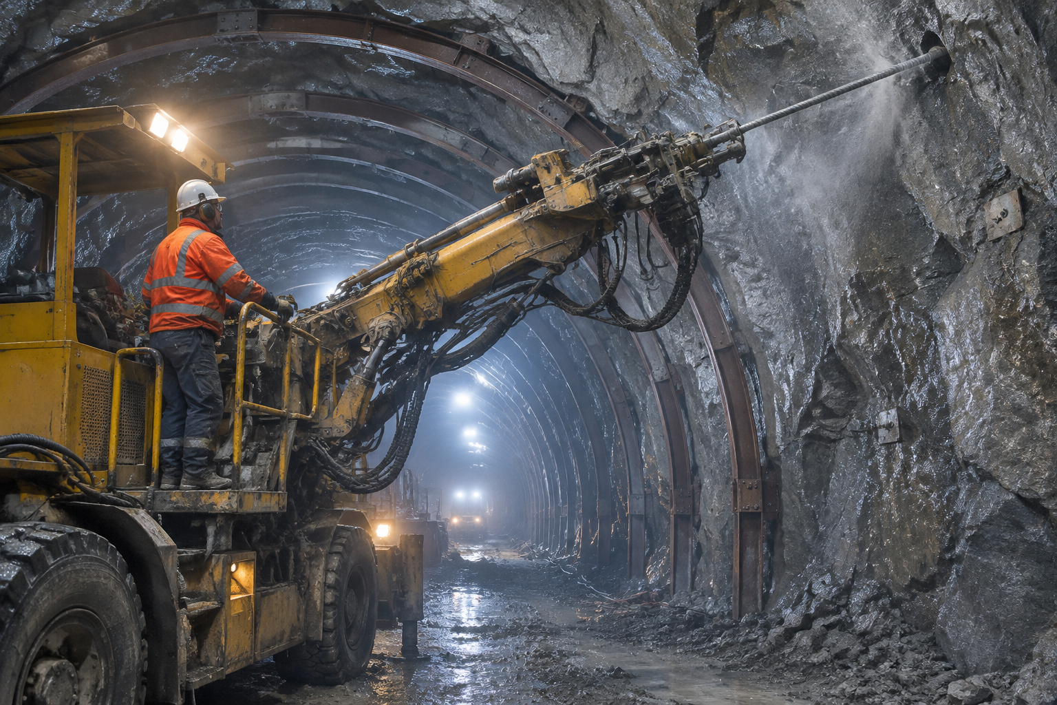
Why Railway Tunnels Are Harder on Anchors Than Other Structures
A railway tunnel concentrates several conditions that are usually separated elsewhere.
The design life is long. Major rail structures are commonly designed for a service life measured in decades rather than years, and permanent support is expected to stay permanent. An anchor that is adequate for a temporary excavation is not automatically adequate for a hundred-year asset, because corrosion, grout deterioration and repeated loading all have time to act.
The loading is repeated. Traffic introduces vibration and cyclic stress into the lining and the surrounding ground. A bolt that performs well in a static test can still loosen at the plate if the seat is poor or the grout column is incomplete.
Water is present. Tunnels intercept groundwater and drain it for the life of the structure. Permanent anchors therefore sit in wet, sometimes chemically aggressive conditions, which turns corrosion protection from a finish specification into a design decision.
Access is constrained. Tunnel work happens in a single-pass, confined envelope. There is often no room for a two-stage operation in which a hole is drilled, inspected, and then loaded with a bar and cartridge. In broken ground the hole may not survive the interval between the two stages at all.
Geometry is awkward. Radial bolts at the face, forepoling at the crown and systematic bolting along the arch all require drilling at angles where a rigid, pre-cut bar is difficult to place and easy to damage.
Put together, these conditions favour a method in which drilling, insertion and grouting are one continuous operation, and in which the installed result can be verified hole by hole.
What the System Actually Consists Of
A self-drilling anchor is best understood as a drill string that becomes the reinforcement.
The core is a hollow bar with a threaded outer profile. A sacrificial drill bit is fitted to the leading end, and the bar itself transmits rotation and percussion to the bit. Flushing medium travels through the hollow core and returns along the annulus, carrying cuttings out of the hole. When the design depth is reached, the bar stays in place and grout is pumped through the same channel, displacing water and filling the annulus from the bottom upward.
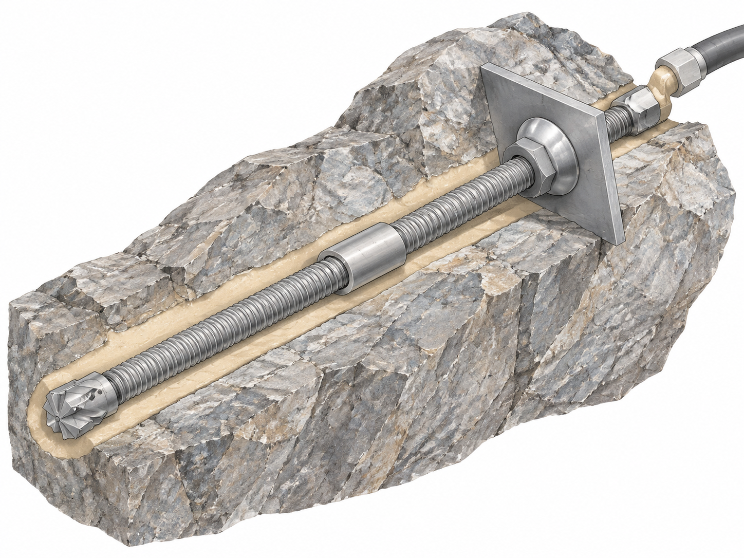
Around that core sit the components that decide whether the system works on site: couplers that join bar lengths where the hole is deep or the ground is collapsing, a plate and spherical washer that let the head seat against an uneven rock face, a nut that transfers load, and injection adapters that allow grout to be placed after the drilling phase. In forepoling applications the same bar may be connected to a steel arch or lattice girder rather than to a simple plate.
The consequence of this architecture is important for procurement. The bar is only part of the load path. The bit determines whether the hole reaches depth in the ground that was logged. The coupler determines whether the load path is continuous. The grout column determines whether load ever reaches the ground. A system assembled from mismatched parts can pass a dimensional check and still fail a pull-out test.
Where Self-Drilling Earns Its Cost
Self-drilling is usually more expensive per metre than a conventional rebar and resin bolt. It earns that premium in ground where a pre-drilled hole cannot be relied on.
Fault and fracture zones. Where the borehole collapses before a bar can be inserted, the ability to drill and leave the bar in the same pass removes the central failure mode of conventional installation.
Weathered rock and soil–rock interfaces. Mixed faces change character within a single round. A system that tolerates variation without changing method is easier to manage than one that requires a different consumable at every chainage.
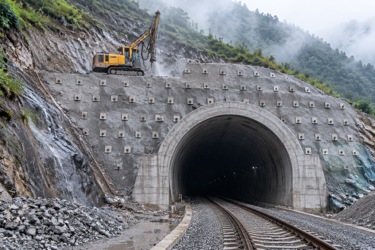
Portal slopes and cut-and-cover. Surface and near-surface work often involves soil, fill and weathered rock, where casing, collapse and groundwater are routine.
Forepoling and umbrella support. Self-drilling forepoles allow the crown to be supported ahead of the face in ground that would not accept a driven pipe. The same bar can later be integrated with the support arch.
Squeezing ground and rehabilitation. In conditions where the support has to be installed close to the face, and in existing tunnels where access is restricted and vibration must be limited, one-pass installation reduces exposure time.
The method has boundaries. In intact, hard rock, a conventional bolt with a resin cartridge is usually faster and cheaper, and the self-drilling premium buys little. Where very high capacities are required, larger-diameter or post-tensioned systems may be more appropriate. In dry ground with a stable borehole, the grouting step becomes a cost without a corresponding benefit.
The Three Controls That Decide Performance
Most failures attributed to "bad bolts" are installation failures. Three controls matter more than the rest.
Drilling. The hole diameter, the bit type, the flushing method and the alignment together determine whether the grout annulus is uniform. Over-drilling in friable rock creates a hole that swallows grout into voids; under-drilling leaves the bar short of the design zone. Rotation and percussion have to be matched to the ground, not simply to the machine's maximum output.
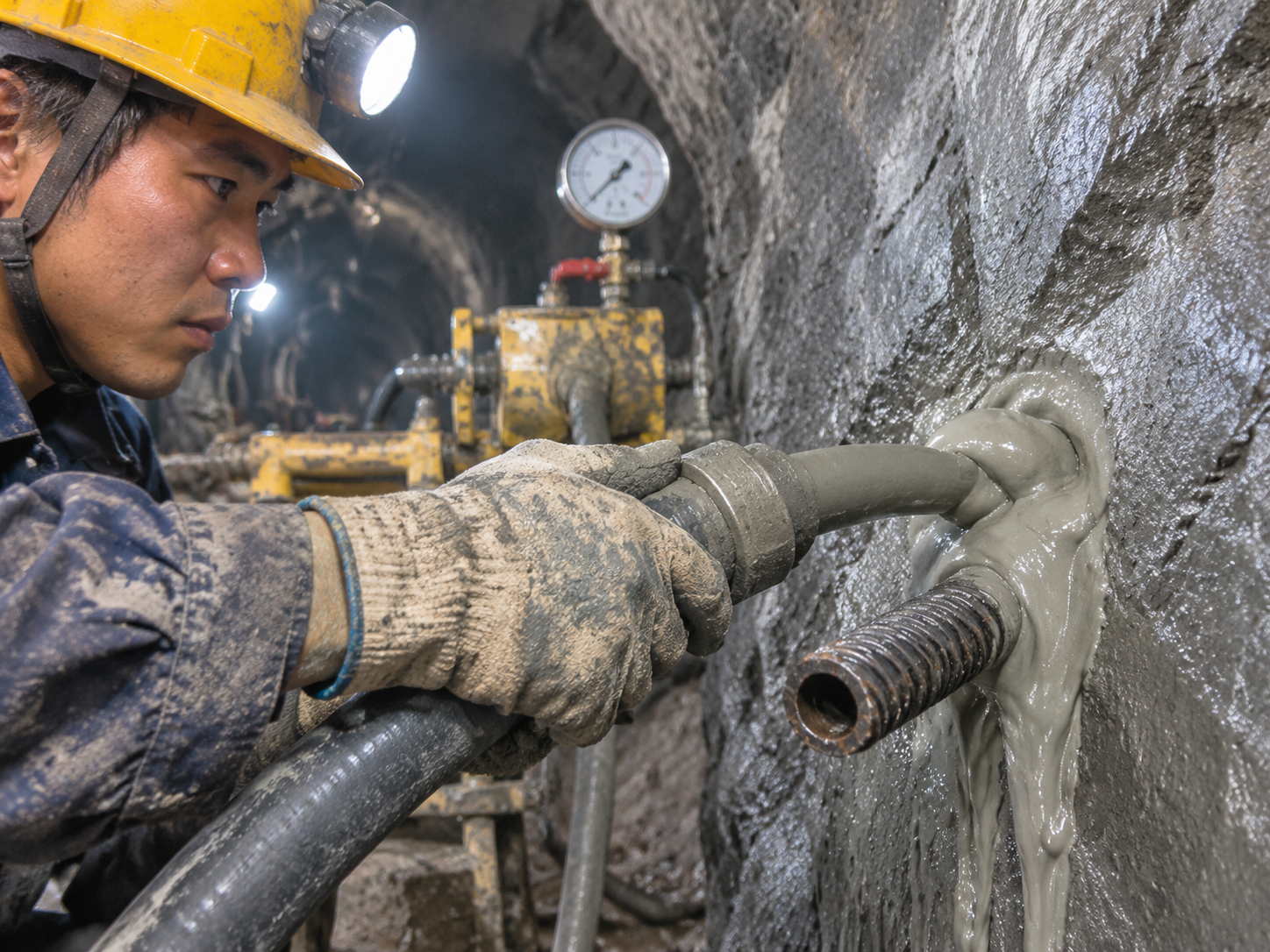
Grouting. Grout has to fill the annulus from the bottom up and displace the flushing water. Volume alone is not proof: the reliable field indicator is return at the collar with grout of the specified consistency. Mix design, water-cement ratio, admixture compatibility and pumping pressure all affect whether the column is continuous. Where voids are known, grout take can exceed the theoretical annular volume by a large margin, and that is a design signal, not a nuisance.
Curing before loading. A pull-out test on green grout measures the grout, not the anchor. The hold period before testing and before applying plate load has to be defined in the method statement and enforced in the shift record.
Torque is a related trap. Nut torque confirms that the plate is seated and the head is engaged; it does not confirm anchor capacity. The two are routinely confused in acceptance conversations.
The Standards Landscape
Self-drilling anchors sit at the intersection of several documents, and the same bar can be governed by different regimes depending on how it is used.
| Function | Typical reference | What it governs |
|---|---|---|
| Geotechnical design | EN 1997-1 (Eurocode 7); GB 50086-2015 | Design actions, resistance, verification and the treatment of anchors as part of the support system |
| Railway tunnel design | TB 10003-2016 | Tunnel support principles, ground classification and design requirements for railway tunnels |
| Execution of ground anchors | EN 1537:2013 | Drilling, installation, grouting, stressing, testing and corrosion protection for ground anchors |
| Execution of soil nails | EN 14490:2010 | Nailing in soil, including installation and testing practice |
| Railway tunnel construction | Q/CR 9604 series | Construction technique and process control for railway tunnels |
| Anchor testing | ISO 22477-5:2018 | Test methods and reporting for anchorages |
| Railway acceptance | TB 10753-2018 | Construction quality acceptance for high-speed railway tunnels |
| Galvanizing | EN ISO 1461 | Hot-dip galvanized coating requirements and inspection |
Three points follow from that table.
First, design and execution are separate approvals. A design calculation that satisfies Eurocode 7 or GB 50086 does not demonstrate that the installed anchor was drilled to the specified depth, grouted to the specified volume or tested at the specified frequency.
Second, the classification matters. EN 1537 is written for ground anchors that are stressed and locked off; a passive self-drilling rock bolt may be specified under EN 14490, under a project-specific rock bolt specification, or under GB 50086 in Chinese practice. The test regime, the corrosion class and the documentation set change with the classification. Buyers who compare quotations without fixing the classification are often comparing different scopes.
Third, product certification is not system certification. A CE-marked bar, a mill certificate and a European Technical Assessment describe specific products and configurations. They do not certify a particular combination of bar, bit, coupler, grout and ground. That combination is what the tunnel actually relies on, and it is normally demonstrated by site-specific investigation and acceptance testing.
What Acceptance Actually Looks At
In a well-run project, the inspector is not asking whether the bolt looks correct. The inspector is reconstructing what happened in each hole.
The record set typically includes the drilling log (position, angle, length, ground condition, water inflow and anomalies), the grout record with mix, volume, pressure and collar return, the pull-out test result with load, hold time and acceptance criterion, the plate seating and torque check, and the traceability chain from bar heat number through coupler batch to grout batch. On larger contracts this is increasingly captured digitally and handed over as an as-built hole map tied to excavation chainage.
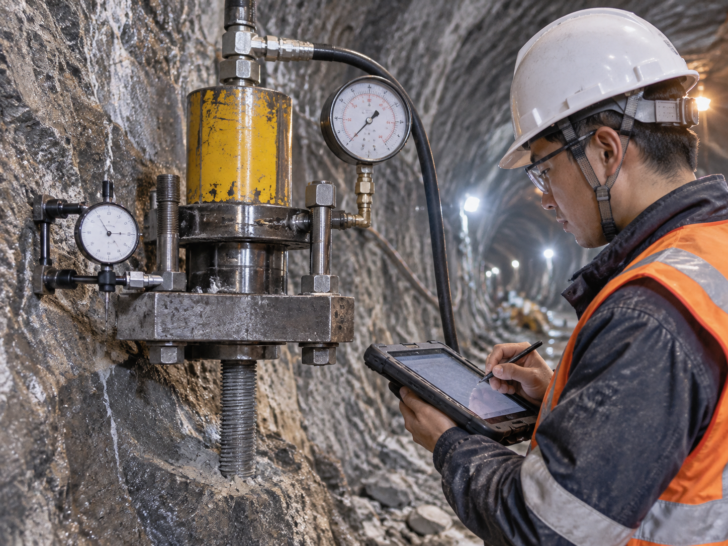
Pull-out testing remains the main direct check, and ISO 22477-5 provides a common basis for procedure and reporting. The proof load, the holding period and the acceptance criterion should come from the project specification, because they depend on whether the anchor is temporary or permanent, tensioned or passive, and on the consequence of failure. Quoting a single multiplier as "the standard" is a reliable sign that the specification has not been read.
What to Lock Down Before Ordering
For a procurement team, the practical checklist is shorter than the standards list but no less important.
- Bar grade, yield strength, outer and inner diameter, wall thickness and elongation, with fatigue data where dynamic loading applies.
- Bit type matched to the logged ground, and a stated rule for what happens when the ground differs from the log.
- Coupler grade and load transfer, plus the maximum unsupported length between couplers.
- Corrosion class for the design life and water chemistry, including whether galvanizing, coating or duplex protection is required and how damaged coating is repaired on site.
- Grout system: cement type, water-cement ratio, admixture, target strength at stated ages, and the acceptance rule for grout take.
- Test regime: frequency per lot or per area, proof load, hold time, acceptance criterion and the action taken on a failure.
- Documentation package: mill certificates, test reports, inspection and test plan, and the as-built record format the client expects.
- Logistics: bar lengths against tunnel access, thread protection in transit, and site storage that keeps couplers and grout components dry.
The Direction of Travel
Two changes are visible across the sector. The first is mechanisation: bolting rigs are increasingly able to capture drilling parameters automatically, which turns the drilling log from a handwritten sheet into a data set that can be compared against the design. The second is service-life thinking: as owners account for the cost of inspection and repair over decades, corrosion protection and verifiable grout cover move up the specification.
Neither change makes the hardware more complicated. Both make the record more important. The suppliers who benefit are those who can hand over a documented system, with bar, consumables, grout, test data and installation support, rather than a pallet of steel.
That is the useful way to read the current interest in self-drilling anchors in railway tunnels. The question is no longer whether a hollow bar can be drilled into broken ground. It plainly can. The question is whether the installed anchor can be shown to be the anchor that was designed, in the hole that was logged, with the grout that was specified. Systems that answer that question are the ones being written into specifications.
Related News
Other news you might be interested in

Self-Drilling Anchor Bolts for Water-Conveyance Tunnel Reinforcement
Self-drilling anchor bolts are useful for water-conveyance tunnel reinforcement when broken or water-bearing ground makes conventional drill-and-insert bolting difficult. By using a hollow threaded bar as both the drilling member and the permanent reinforcement, the system removes the separate bolt-insertion step and provides a channel for grouting through the same bar.For a water-conveyance tunnel, that installation advantage matters. Headrace, tailrace, diversion, irrigation and water-supply tunnels can pass through fault zones, weathered rock, weak interlayers and interconnected fractures. Groundwater may enter the excavation, boreholes may deteriorate after drilling, and support must be coordinated with drainage, waterproofing and the final lining.

What Is a Split Set Mining System and How Is It Different from Other Rock Bolts?
A split set is often described as a rock bolt, but in mining it is more useful to think of it as a support system. The steel tube is the most visible part. The way it performs also depends on the drilled hole, the bearing plate, the installation adapter, the drilling equipment, the surface support and the checks made underground. That distinction matters when a project compares rock bolts. Two quotations can list a similar diameter and length, yet propose different load-transfer mechanisms, different hole requirements and different installation procedures. A split set is not a resin bolt with the resin removed. It is not a mechanical expansion-shell bolt, a self-drilling hollow bar, a water-inflatable tube or a cable bolt. Each product family solves a different part of the ground-support problem.
Want to know more?
Get in touch with us for more information about our services and products.