

Common Failures For Hollow Anchor Bar Tunnel Construction

Dayang Yang
AuthorWith over 15 years of experience in the production and sales of ground anchoring and mining support products, we operate our own rock bolt and accessory manufacturing facility with stable large-scale production capacity. We are specialists in rock bolts, resin cartridges, anchor cables, bearing plates, and customized ground anchoring products for mining support and geotechnical anchoring solutions.
Hollow anchor bars are one of the most practical support elements in tunnel construction. They combine drilling, grouting, and anchoring in a single steel element, making them suitable for fractured rock, squeezing ground, and locations where installing a casing would be difficult or slow. That integration is also what makes them sensitive to detail. A small deviation in water-cement ratio, hole alignment, grout volume, or thread condition can turn a designed support element into a weak point.
Most anchor failures are not sudden events. They begin as small process deviations that remain invisible until the anchor is loaded or the tunnel is exposed to groundwater. This article examines the most common failure modes of hollow anchor bars in tunnel construction, explains their causes and consequences, and sets out practical prevention measures.
Introduction to Hollow Anchor Bars in Tunnel Construction
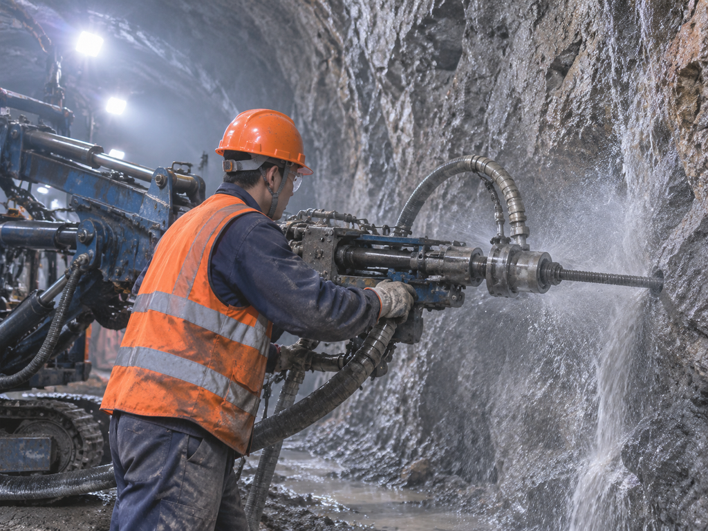
A hollow anchor bar is a steel bar with a central bore and a continuous thread along its length. During installation, the bar acts as the drill string; after drilling, grout is injected through the bore and fills the annular space between the bar and the rock. The result is a combined drilling, grouting, and anchoring system that can be installed quickly and in confined spaces.
The system is particularly useful in weak, fractured, or water-bearing ground. Conventional solid bars often require a separate drilling step, a casing to keep the hole open, and a separate grouting operation. In collapsing ground, the hole may close before the bar can be inserted. Hollow anchor bars reduce that risk because the bar is already in the hole while drilling proceeds.
However, the same characteristics that make hollow anchor bars efficient also create specific failure risks. The internal bore can block. The external thread can be damaged. Grout may fail to fill the annulus. The bar may be installed at the wrong angle or to an insufficient depth. This article groups these risks into eight common failure modes and then describes the process controls that keep them under control.
Common Failures in Hollow Anchor Bar Construction
The failure modes below can be grouped into four broad areas: incorrect material proportioning, geometric deviation, incomplete grouting, and structural or durability problems. In practice, these areas are connected. A shallow hole can lead to excessive grout take. A blocked bore can lead to incomplete encapsulation. Incomplete encapsulation can accelerate corrosion. The purpose of classifying failures is not to treat them separately, but to identify where the installation process is most vulnerable.
Incorrect Water-Cement Ratio
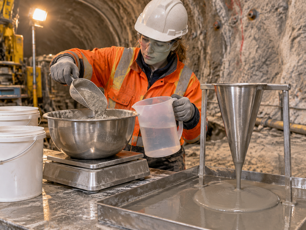
Typical causes. The water-cement ratio is often controlled manually on site. Variations in water volume, cement weight, mixing time, and ambient temperature can all change the actual ratio. Operators may also add water to improve pumpability without adjusting the cement content.
Consequences. A grout that is too thin can segregate, bleed, and lose bond strength. A grout that is too thick can block the bar bore, increase pumping pressure, and leave voids in the annulus. Both conditions reduce load transfer between the bar and the rock. Inconsistent grout also makes pull-out results difficult to interpret.
Prevention. Use calibrated measuring equipment and, where possible, automated mixing. Check each batch with a flow cone or slump test, and record the result against the approved mix design. Adjust the mix only within the limits set by the project specification, and account for temperature and delivery time. Out-of-specification grout should be discarded rather than diluted or re-tempered.
Horizontal Angle Misalignment
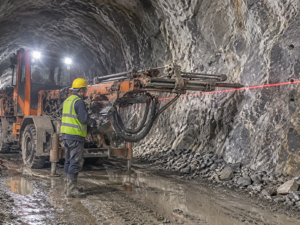
Typical causes. Angle errors usually come from rig setup, operator technique, or an uneven tunnel face. The drilling rig may not be aligned to the designed reference, or the operator may estimate the angle without a positive check. In curved tunnel sections, the reference direction can also shift from hole to hole.
Consequences. An anchor installed at the wrong horizontal angle may cross a joint or weak zone at a shallow angle instead of anchoring beyond it. This reduces the effective bond length and can create uneven stress distribution around the tunnel opening. In vault areas, misalignment is also associated with roof leakage and local instability.
Prevention. Use laser guides, angle indicators, or fixed drilling jigs. Mark the reference direction on the face before drilling, and check the rig alignment before each hole. Operators should be trained to verify the angle against the tunnel contour rather than relying on visual estimation. A short check before drilling is far cheaper than a failed anchor after grouting.
Positioning Deviation and Insufficient Hole Depth
Typical causes. Position errors can result from inaccurate marking, rushed layout, drilling drift, or movement of the drilling rig. Insufficient depth may be caused by hole collapse, a blocked bit, or using a bar that is shorter than the design length.
Consequences. A misplaced anchor may miss the intended support zone entirely. A shallow anchor has less embedment and therefore less bond length, which reduces pull-out capacity. If the hole is not cleaned properly, the bar may not reach the intended depth even when the drilled length appears correct.
Prevention. Set out holes with a total station or laser reference, and mark both position and depth. Measure drilled depth before installation, and use a depth marker on the drill string. Clean the hole and confirm that it remains open. Use the specified bar length and verify it before grouting. For critical support areas, record the actual position and depth of every anchor.
Inadequate Grouting
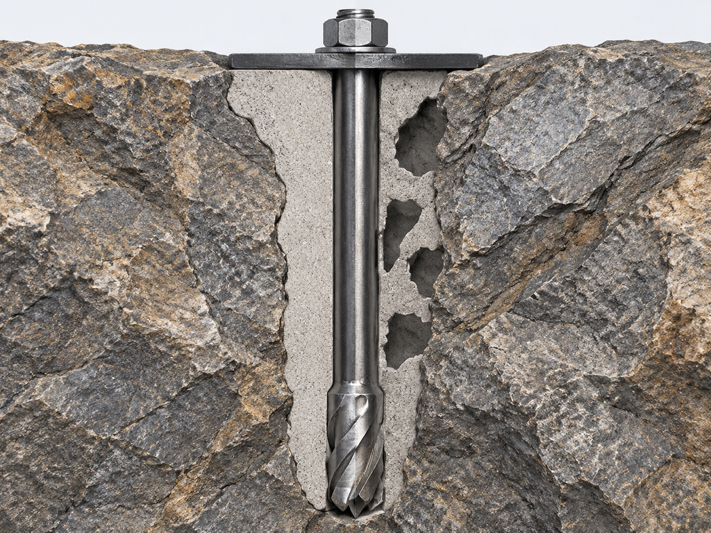
Typical causes. Incomplete grouting can result from an underestimated grout volume, low pumping pressure, air pockets, leakage through cracks, or stopping injection too early. A blocked bore, a poor connection at the bar head, or incorrect venting can also prevent the annulus from filling completely.
Consequences. Voids and incomplete encapsulation reduce the bond between the bar and the rock. They also create paths for water and oxygen, which increases the risk of corrosion. The anchor may pass a short-term pull-out test but perform poorly over the design life of the tunnel. In severe cases, the bar is only partially bonded and carries load over a much shorter length than assumed.
Prevention. Calculate the theoretical grout volume for each hole and compare it with the actual volume. Grout from the bottom of the hole upward, maintain a stable pressure, and confirm grout return where the installation method allows it. Use appropriate venting and check connections before injection. Record pressure, volume, and injection time for every anchor. If the volume is significantly outside the expected range, stop and investigate before proceeding.
Corrosion and Material Degradation
Typical causes. Tunnel environments can be aggressive. Chloride-bearing groundwater, sulfate attack, stray currents, and alternating wet and dry conditions can all accelerate corrosion. Damage to a protective coating during handling or installation creates a local initiation point. Incomplete grout cover leaves the bar exposed to the environment.
Consequences. Corrosion reduces the cross-sectional area of the bar and can damage the thread, the weakest point in the load path. A corroded anchor may lose capacity gradually and fail without obvious warning. Corrosion also creates a water path along the bar, which can lead to staining, leakage, and deterioration of the surrounding support system.
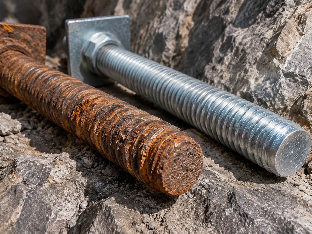
Prevention. Select the bar and coating system for the expected groundwater chemistry. Hot-dip galvanizing, epoxy coating, and stainless steel are available for different exposure conditions. Maintain the specified grout quality and pH, because alkaline grout helps passivate the steel surface. Ensure full encapsulation and seal the plate, nut, and exposed thread. Protect coated bars during transport and installation, and inspect them before grouting.
Bar Fracture and Thread Failure
Typical causes. Bar fracture can result from overloading, excessive bending during installation, or fatigue under repeated loads. Thread failure is often caused by damaged threads, mismatched couplers or nuts, insufficient thread engagement, or excessive torque during assembly.
Consequences. A fractured bar or stripped thread breaks the load path between the bearing plate and the anchored length. The anchor may appear to be installed correctly but carry little or no load. In the worst case, failure occurs suddenly when the support is most needed.
Prevention. Use the specified bar grade and diameter, and do not substitute components without approval. Protect threads during transport and handling. Use matching couplers, nuts, and plates, and follow the recommended torque. Avoid bending the bar to fit an misaligned hole; correct the hole or use an appropriate transition component instead. Inspect threads before installation and reject damaged bars.
Plate, Nut, and Bearing Failure
Typical causes. Bearing failure often begins with an undersized plate, a plate that is too thin, or poor contact between the plate and an uneven rock surface. Point loading can deform the plate or crush the rock beneath it. Insufficient thread engagement or a loose nut can also allow the anchor head to move.
Consequences. The plate may punch into the rock, deform, or crack the surrounding shotcrete. Load is transferred over a smaller area than assumed, and the anchor may lose tension. In tunnels with moving ground, a loose or deformed bearing plate can allow progressive movement and visible cracking.
Prevention. Select the plate size and thickness for the rock strength and the design load. Use a domed washer or grout pad to improve contact on uneven surfaces. Prepare the bearing surface where necessary, and tighten the nut to the specified torque. Confirm full thread engagement and protect the plate and nut from corrosion. Inspect installed plates after shotcreting and during routine tunnel inspections.
Hole Instability and Bar Jamming
Typical causes. In collapsing or squeezing ground, the hole may close before the bar is fully inserted. Inadequate flushing can leave cuttings in the hole and increase friction. A worn or incorrect bit, excessive rotation, or a delay between drilling and grouting can also cause the bar to jam.
Consequences. A jammed bar may not reach the design depth, and the grout channel may become blocked. The anchor is often abandoned, leaving a gap in the support pattern. Rework costs time and may require drilling a new hole nearby, which can further disturb the ground.
Prevention. Use a self-drilling system that allows the bar to be installed while drilling, rather than drilling a hole and inserting the bar afterward. Select the bit for the ground condition, maintain controlled flushing, and avoid unnecessary delays. In squeezing ground, monitor hole conditions and adjust the drilling and grouting sequence. If a bar cannot be installed to depth, record the location and replace the anchor according to the design procedure.
Construction Process Management Strategies
Because most hollow anchor bar failures are process-driven, the most effective controls are also process-based. The following measures should be treated as a single quality system rather than separate checks.
Staffing and Monitoring
Assign clear responsibilities for drilling, grouting, inspection, and record keeping. Operators should be trained on the specific bar system and on the failure modes described above. A dedicated inspector should check hole position, angle, depth, grout ratio, and injection records before the next stage proceeds.
Real-time monitoring is increasingly practical on tunnel sites. Digital logs of hole location, drilling time, grout volume, and pressure make it easier to detect anomalies early. Shift handover should include a review of incomplete anchors and any deviations from the approved procedure.
Raw Material Inspection
Inspect bars for straightness, dimensions, thread condition, and coating damage. Confirm that mill certificates and batch records match the delivered material. Check cement for lumps, contamination, and storage damage. Verify that additives are within their shelf life and are stored according to the manufacturer’s instructions.
Material traceability matters. If a later pull-out test fails, the ability to trace the bar, cement batch, and grout additive back to the installation record makes investigation much faster.
Equipment and Testing
Calibrate drilling rigs, grout pumps, pressure gauges, and flow meters at defined intervals. Check alignment devices before each shift. Maintain spare bits, packs, and pump components so that a breakdown does not leave a hole open for an extended period.
Equipment condition directly affects anchor quality. A worn bit can produce an undersized or irregular hole. A drifting pressure gauge can cause under- or over-grouting. A blocked pump can interrupt injection before the annulus is full.
Cement Slurry Consistency
Control the water-cement ratio at the mixer, not at the hole. Use calibrated water and cement measurement, follow the specified mixing time, and test consistency with a flow cone or slump test at the required frequency. Record the results and the batch number.
Temperature affects setting time and flowability. In hot conditions, grout may thicken faster than expected; in cold conditions, setting may be delayed. Adjust the mix within the approved limits and do not use grout that has exceeded its usable life.
Grouting Process Optimization
Clean the hole before grouting and confirm that the grout path is open. Inject grout in a controlled sequence, maintain the specified pressure, and monitor the return. For fractured rock, consider the use of retarders or stage grouting to improve penetration and reduce the risk of premature setting.
Record the actual grout volume for each anchor and compare it with the theoretical volume. A significantly low volume may indicate a blockage or leakage; a significantly high volume may indicate a void, a connected fracture, or an oversized hole. Both cases require investigation.
Pull-Out Testing and Quality Acceptance
Pull-out testing verifies that the installed anchor can transfer load to the ground. The test frequency, load levels, and acceptance criteria should follow the project specification. A common approach is to test a representative sample of production anchors, together with verification tests in critical areas.
The test should be performed with calibrated equipment and recorded properly. Results should include the anchor location, installation date, test load, displacement, and failure mode if applicable. A failed test should trigger an investigation of the installation records and, where necessary, additional testing or remedial anchors.
Pull-out testing is not only an acceptance tool. When results are reviewed as a set, they can reveal trends: a cluster of low-capacity anchors may point to a grouting problem, a depth problem, or a change in ground conditions.
Solutions and Innovations: Sinorock’s Self-Drilling Hollow Anchor Bar Systems
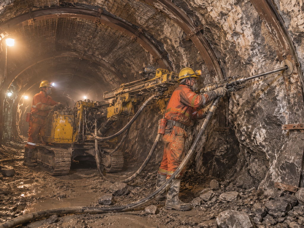
Many of the failures described above can be reduced by choosing an installation system that removes unnecessary steps. Sinorock’s self-drilling hollow anchor bar systems are designed around this principle: the bar drills, grouts, and anchors in one continuous operation, reducing the time during which an open hole can collapse or deteriorate.
Key Features
- One-piece hollow bar with continuous thread. The bar can be coupled to the required length without welding, and the thread provides a reliable connection for drilling, grouting, and bearing components.
- Drilling, grouting, and anchoring in one operation. The bar is installed while drilling, which is particularly useful in collapsing ground where a conventional hole would close before insertion.
- Grout injection through the bar. Grout fills the annular space from the bottom of the hole, improving encapsulation and reducing the risk of voids.
- Suitable for weak and fractured ground. The system reduces the need for casing and can be used in squeezing, weathered, or broken rock masses.
- Corrosion protection options. Galvanized, epoxy-coated, and stainless steel variants are available for different groundwater and exposure conditions.
- Compatible accessory range. Plates, nuts, couplers, and drill bits are matched to the bar system, reducing the risk of thread mismatch and improper load transfer.
Case Study: Application in Squeezing Ground
In a representative tunnel section in squeezing ground, the contractor encountered repeated hole collapse with a conventional drill-and-insert method. Holes closed before the anchor could be installed, and several anchors could not be grouted to the design volume. The result was a growing number of abandoned holes and inconsistent pull-out results.
The contractor switched to Sinorock self-drilling hollow anchor bars. The bar was drilled into place and grouted through the bore without a separate casing operation. Grout volume and pressure were recorded for each anchor, and pull-out tests were performed on a sample of installed anchors.
The observed benefits were practical rather than theoretical: fewer abandoned holes, more consistent grout return, and a shorter installation cycle in the difficult section. The case also reinforced a broader lesson. In squeezing ground, the anchor system and the installation method cannot be treated as separate decisions. The ability to install the bar before the hole closes is part of the support performance.
Conclusion
Hollow anchor bars are effective tunnel support elements, but their performance depends on a chain of details: the bar, the hole, the grout, the bearing components, and the installation record. The most common failures are therefore predictable. Incorrect water-cement ratio, angle misalignment, shallow or misplaced holes, incomplete grouting, corrosion, bar or thread damage, bearing failure, and hole instability all have identifiable causes and practical controls.
The priority is not to inspect failures after they occur, but to control the process before the anchor is loaded. That means checking materials, setting out holes accurately, maintaining the specified grout ratio, recording injection parameters, and verifying performance with pull-out tests. When these controls are applied consistently, the anchor system can perform as intended over the design life of the tunnel.
For projects in weak, fractured, or squeezing ground, a self-drilling hollow anchor bar system can remove several of the most common failure paths at once. The right system, combined with disciplined installation and testing, provides a more reliable support solution than either element alone.
Related News
Other news you might be interested in

How do concrete anchor bolts improve foundation stability?
A concrete anchor bolt is a small part of a foundation, but it decides whether the foundation and the structure above it behave as one system. The bolt does not make the concrete stronger or the soil stiffer. It provides a controlled load path between the steel structure, the base plate, the concrete, and—when the anchor is designed to reach it—the deeper ground.In this article, the term covers cast-in anchor rods, post-installed mechanical or adhesive anchors, and post-tensioned bars or strand anchors used to tie a structure or foundation element into concrete.That distinction is the key to answering the question. Anchor bolts improve foundation stability by resisting uplift, shear and overturning, maintaining clamping force, helping to distribute concentrated loads, and tying the foundation to a competent bearing stratum. They cannot compensate for an undersized footing, a poor subgrade, or a missing reinforcement detail.

Split Set Bolts, Resin Bolts, and Cable Bolts: Choosing the Right Ground Support System
Three bolts can be quoted for the same roadway and still do different jobs. A split set bolt grips the borehole along its length and begins to carry load as it is driven. A resin bolt bonds a steel bar to the rock and can be tensioned against a plate. A cable bolt anchors a flexible, high-capacity tendon deep behind the excavation. They are not three grades of the same product. They are three ways of building a support system.
Want to know more?
Get in touch with us for more information about our services and products.