

Application of Self-Drilling Anchor Bolts in Bridge Reinforcement

Dayang Yang
AuthorWith over 15 years of experience in the production and sales of ground anchoring and mining support products, we operate our own rock bolt and accessory manufacturing facility with stable large-scale production capacity. We are specialists in rock bolts, resin cartridges, anchor cables, bearing plates, and customized ground anchoring products for mining support and geotechnical anchoring solutions.
Bridge rehabilitation rarely starts from a clean drawing. It starts from an abutment built before anyone kept as-built records, a wing wall that has rotated away from the deck, a four-hour possession window, and a borehole log that describes the fill as "variable". That is the environment in which self-drilling anchor bolts have moved out of tunnel support and into bridge repair.
The logic of the method is simple: a hollow threaded bar is the drill string, the grout channel and the reinforcement at the same time. The hole cannot collapse before the bar goes in, because the bar is already in it. The grout is placed from the bottom up through the same path, so the annulus is filled before the bar is loaded. In ground that will not hold a borehole, that sequence removes the most common failure mode of conventional anchoring.
Bridges add a second layer of difficulty. The anchor has to be installed through, under or beside a structure that is still carrying traffic, in a space that was never designed for drilling equipment, into a material whose condition is only partly known. The method survives that environment, but only when the specification addresses access, corrosion and verification as carefully as it addresses bar strength.
Why Bridge Anchoring Is Not Tunnel Anchoring
A tunnel face is a known, if uncertain, geology. A bridge abutment is a structure, a foundation and a retained earth mass at the same time, and the drawings rarely describe all three.
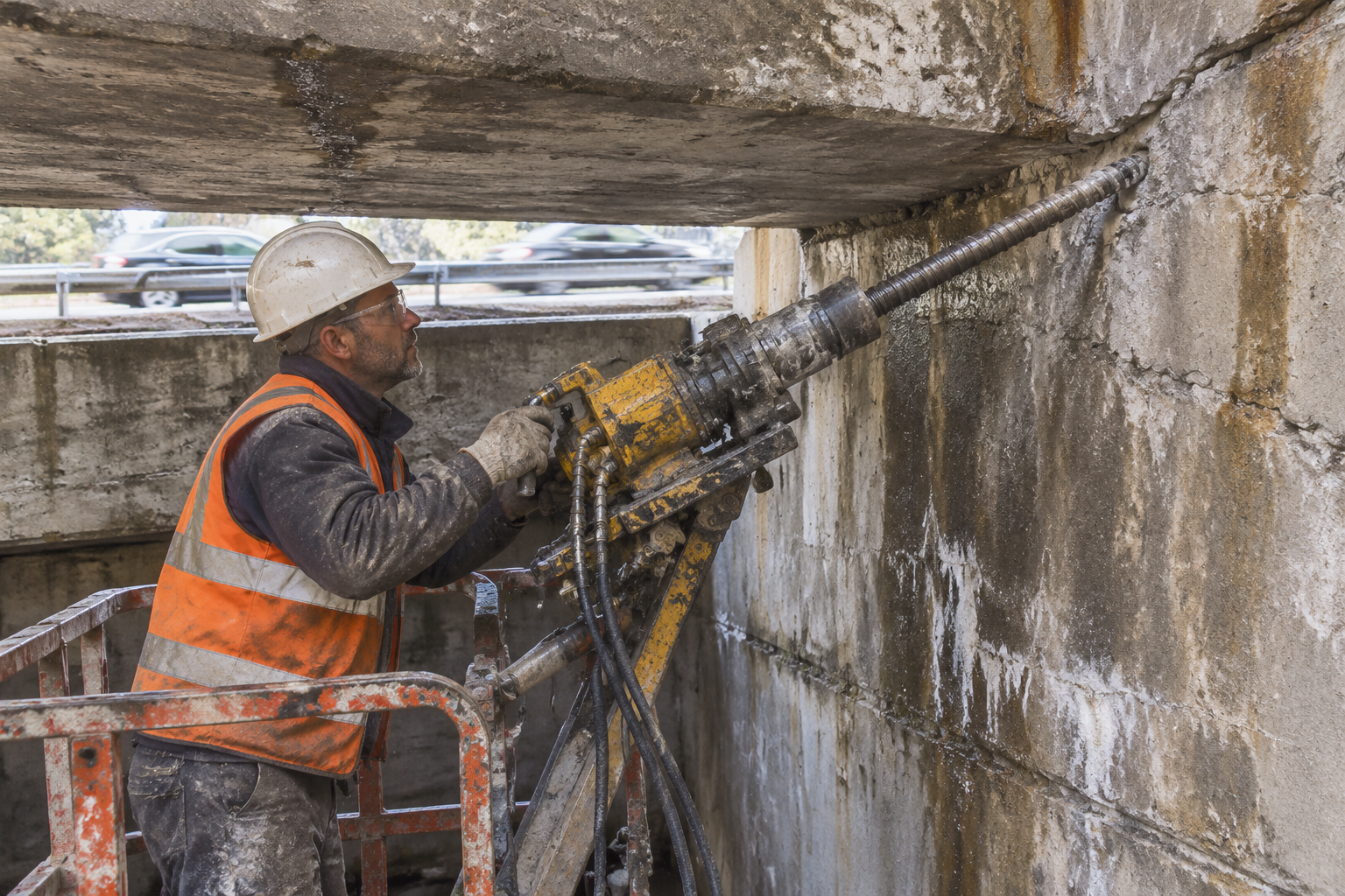
The first constraint is headroom. Work under a deck may allow one metre of clearance, sometimes less. Equipment has to be compact, often hand-held, and capable of drilling at upward angles in a confined space. A rig that performs well in a tunnel can be unusable here.
The second is live traffic. Drilling into a loaded structure introduces vibration, and vibration is measured, because the structure is being monitored for movement while the work proceeds. Closure windows are short, which pushes the method toward operations that finish in one pass rather than three.
The third is the unknown structure. Reinforcement may be congested exactly where the anchor needs to go. A masonry arch may contain voids behind the ring. A footing may be larger, deeper or weaker than the drawing shows. The first hole is an investigation, not a production hole.
The fourth is exposure. Bridge anchors sit in splash zones, de-icing salt, wet joints and, on electrified railways, possible stray current. Unlike a tunnel anchor that can be inspected from a walkway, a bridge anchor is often buried in an abutment and cannot be examined again. Corrosion protection therefore has to be designed for the full service life, not for the construction period.
The fifth is consequence. A failed ground anchor behind a slope is a slope problem. A failed anchor in a bridge abutment is a structural and public-safety problem, and the acceptance evidence has to be strong enough to survive an audit years later.
Five Situations Where the Method Fits
Self-drilling anchors are not a universal replacement for conventional bridge repair. They earn their cost in five recurring situations.
Abutment and wing-wall tie-back. Where a wall has rotated or bulged, anchors are drilled through the wall into the retained fill or rock and grouted to form a tie-back. The ability to drill through a structure and continue into uncertain ground without a separate casing operation is the main advantage. Temporary tie-backs during bearing replacement follow the same logic, with the anchor removed or de-tensioned at the end of the stage.
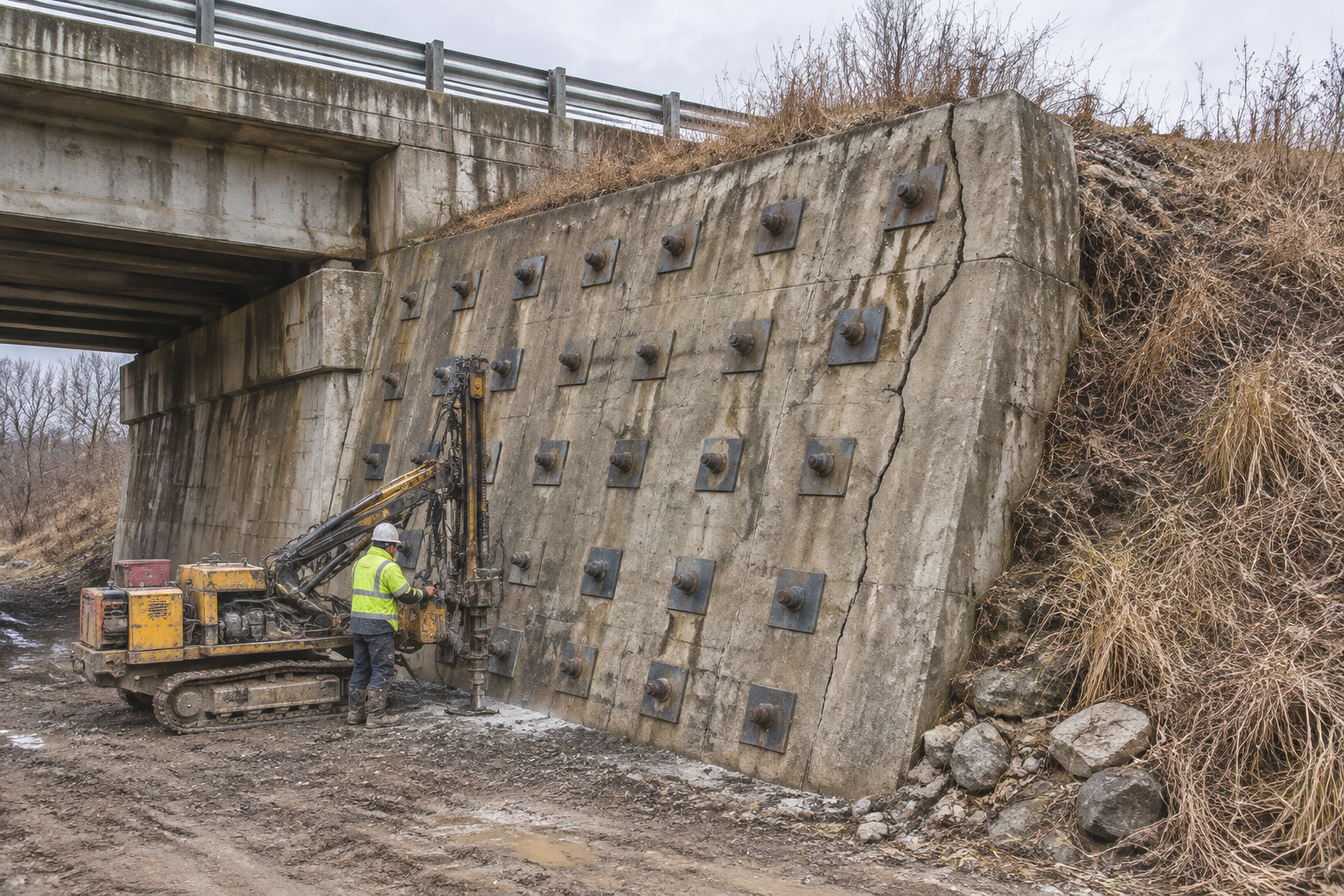
Foundation underpinning and micropile connection. When a footing has settled or a new load has to be transferred, anchors or micropiles are drilled through the existing concrete. Drilling through reinforcement and then grouting in one pass avoids leaving an open hole beneath a loaded footing.
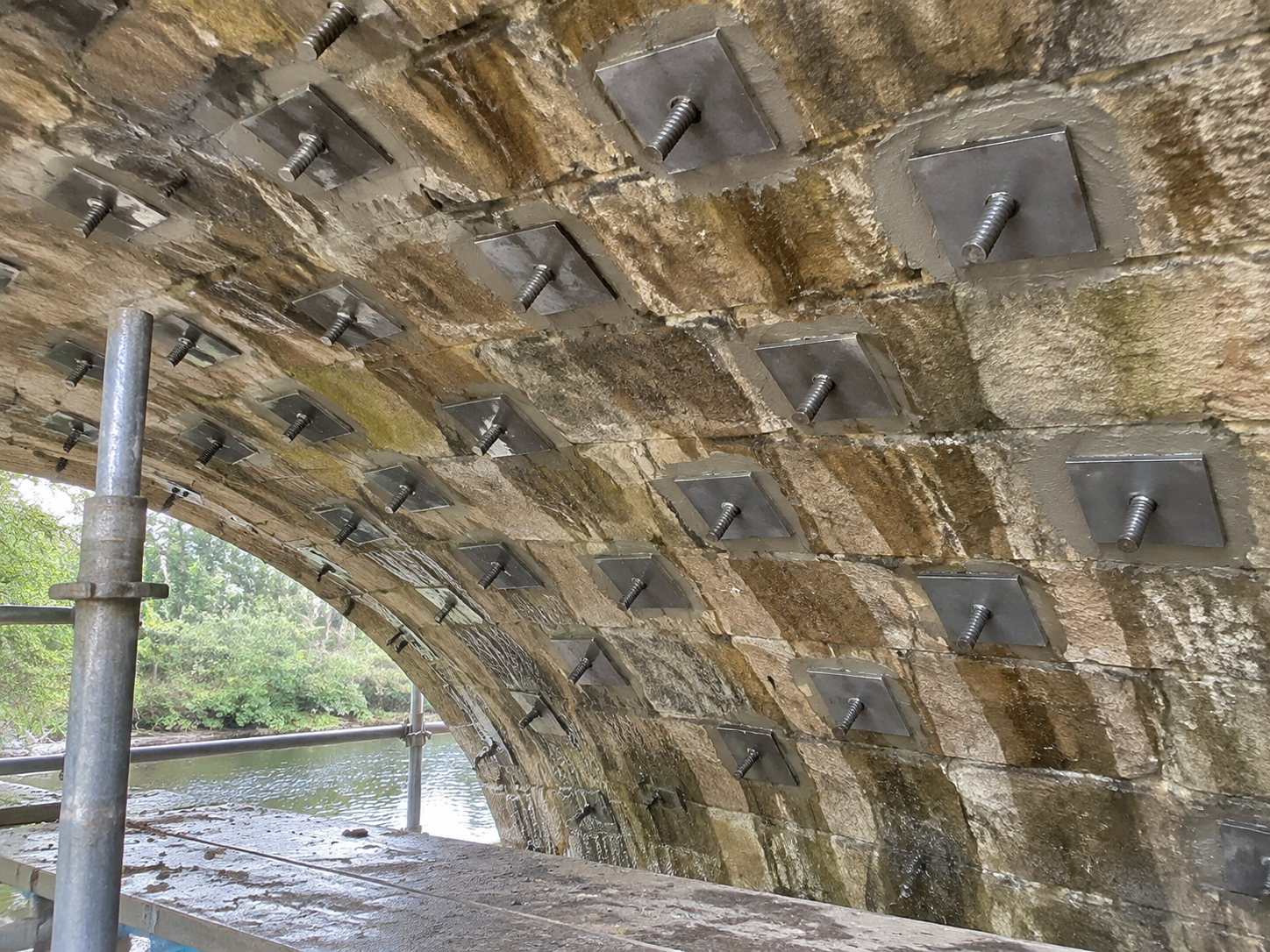
Masonry and concrete arch barrels. Radial anchors through the arch ring tie the barrel back to sound backing or to a new concrete layer. In masonry, the drill may pass through stone, mortar and voids within a single metre, which is precisely the condition where a pre-drilled hole is unreliable.
Bridge-end embankments and approach slopes. The soil mass behind an abutment is often the weakest part of the asset. Anchors installed from a restricted platform, or from the slope itself, stabilize the approach without closing the structure.
Scour repair and footing confinement. After scour has exposed or undercut a footing, a common repair is to jacket the footing and anchor the jacket into competent ground below. The anchor has to be installed in wet, disturbed material, often with limited access from a bank or a barge.
Each of these shares a feature: the anchor crosses a boundary between a built structure and natural ground. That boundary is where conventional drilling most often fails.
The System, and What the Numbers Mean
The hardware is a hollow bar with a continuous thread, a sacrificial bit at the leading end, a grouting stopper at the collar, a bearing plate, a nut and coupling sleeves for extension. Grout is pumped through the bar and exits at the bit end, filling the annulus from the bottom upward. The stopper holds pressure at the collar and limits backflow.
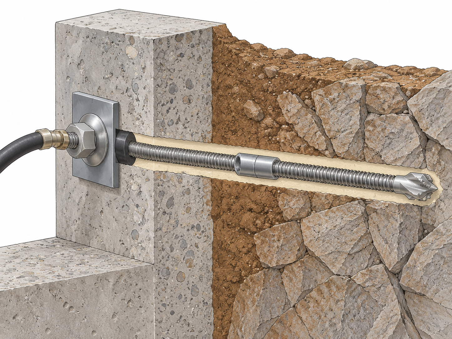
In the CQ Rockbolt range, the bars run from R25 to T76, with nominal diameters of 25, 32, 38, 51 and 76 mm and inner grouting diameters from 13 to 42 mm. Tensile strength is stated as at least 550 MPa and yield strength at least 350 MPa across the range, with standard lengths of 2, 3, 4 and 6 m and matched bit diameters from 32 to 114 mm. Coupling sleeves are specified to transfer no less than the bar body, which matters when a bridge anchor has to be built up in stages under a low deck. Recommended grouting pressure is 0.5 to 2.0 MPa, adjusted for ground and grout.
Those numbers describe a bar. The bridge-specific decisions are elsewhere: which diameter fits the drill and the access, whether the coupler can pass the collar, how the plate seats on an uneven stone or spalled concrete face, and whether the corrosion system survives the exposure class.
Drilling Through Something That Is Already Built
Installation through an existing structure is a sequence of small decisions, and most of them are about avoiding damage rather than achieving capacity.
The first is detection. Reinforcement is located before drilling, by drawing review, cover meter or ground-penetrating radar, and confirmed with a trial hole. Cutting a main bar in a pier or abutment is not an acceptable way to make room for an anchor. Where a bar must be crossed, the anchor is repositioned, or the hole is cored and the bar is protected and reinstated under the structural engineer's instruction.
The second is alignment. The exit point matters as much as the entry point. An anchor that leaves the back of an abutment too high misses the retained mass; one that leaves too low may enter a void or a service duct. In masonry, the drill can follow a mortar joint, so the line is checked as the hole advances rather than only at the start.
The third is water and spoil. Wet drilling produces a slurry that has to be contained, particularly where the work is over a watercourse, a railway or a live carriageway. Flush water is collected at the collar, not allowed to run through the structure.
The fourth is movement. Crack gauges, tilt sensors or prism monitoring are read before, during and after drilling, with trigger levels agreed in advance. If the structure responds, the sequence stops. This is the control that distinguishes bridge work from open-site anchoring.
The fifth is grout. Grout is pumped until return at the collar matches the specified consistency. In a masonry arch, the take can be many times the theoretical annular volume because grout is filling voids behind the ring. That is information about the structure, and it should be recorded and passed to the designer rather than treated as waste.
Corrosion Is the Design Driver
For a permanent bridge anchor, the corrosion system is not a coating choice at the end of the specification. It determines whether the anchor can be relied on at year thirty.
Three exposures dominate. Chloride from de-icing salt and marine spray drives pitting and crevice attack at the plate and the first metre of bar. Wet joints and drainage paths create alternating wet and dry zones. Electrified railways introduce stray current, which can accelerate corrosion on metallic anchors that are electrically continuous with the structure.
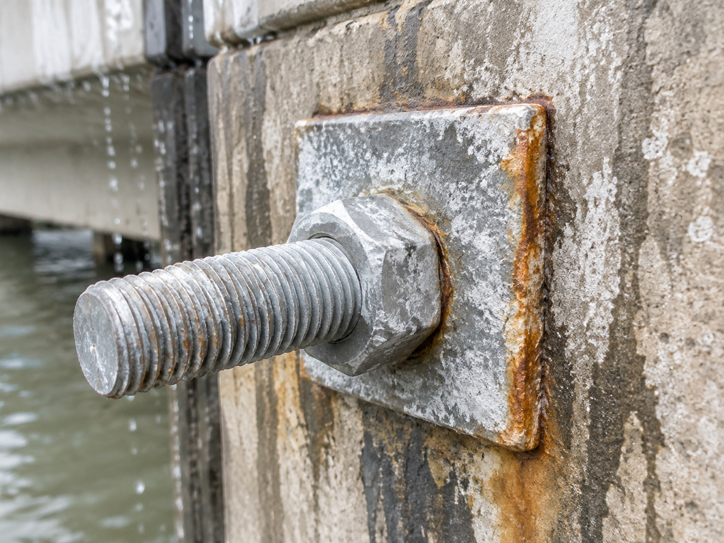
The available measures are familiar: hot-dip galvanizing to EN ISO 1461, epoxy or other barrier coatings, duplex systems, stainless steel for the most aggressive locations, and a cementitious or grout cover that keeps chlorides away from the steel. EN 1537 describes double corrosion protection for permanent ground anchors, and that concept, rather than a single coating thickness, is the useful reference when the design life is measured in decades.
Two practical points are often missed. First, coating damage at the coupler and at the plate is where corrosion starts; repairs have to be specified, not left to site discretion. Second, an anchor that is electrically bonded to a structure carrying stray current needs an isolation detail or a cathodic protection assessment, and that decision belongs to the bridge engineer, not the anchor supplier.
Standards and the Approval Route
Bridge anchoring draws on three families of documents, and a project usually has to satisfy more than one.
| Function | Typical reference | What it governs |
|---|---|---|
| Ground anchor execution | EN 1537:2013 | Drilling, grouting, stressing, testing and corrosion protection for ground anchors |
| Micropile execution | EN 14199:2015 | Execution of micropiles used for underpinning and load transfer |
| Anchor testing | ISO 22477-5:2018 | Test methods and reporting for anchorages |
| Concrete repair and anchoring | EN 1504-6 | Anchoring of reinforcing steel in repaired concrete structures |
| Repair of existing concrete | ACI 562 | Assessment, repair and rehabilitation of existing concrete structures |
| Chinese concrete strengthening | GB 50367-2013 | Design of strengthened concrete structures, including anchorage |
| Chinese highway bridge strengthening | JTG/T J22-2008 | Design of highway bridge strengthening works |
| Galvanizing | EN ISO 1461 | Hot-dip galvanized coating requirements and inspection |
The important distinction is between product approval and system approval. A CE-marked bar, a mill certificate or a type approval describes a product or a tested configuration. It does not approve a specific anchor installed at a specific angle into a specific abutment. That approval comes from the bridge owner's engineer, on the basis of a design, a method statement and site-specific test results.
The second distinction is between design and execution. A calculation that satisfies Eurocode 7, GB 50367 or JTG/T J22 does not demonstrate that the hole reached the design depth or that the annulus is full. In bridge work the two are audited separately, and both are required.
What Acceptance Looks Like
Acceptance testing on a bridge anchor is usually a proof load test, with the load, hold period and movement criterion set by the project specification. The test is performed on cured grout. Testing early measures the grout, not the anchor.
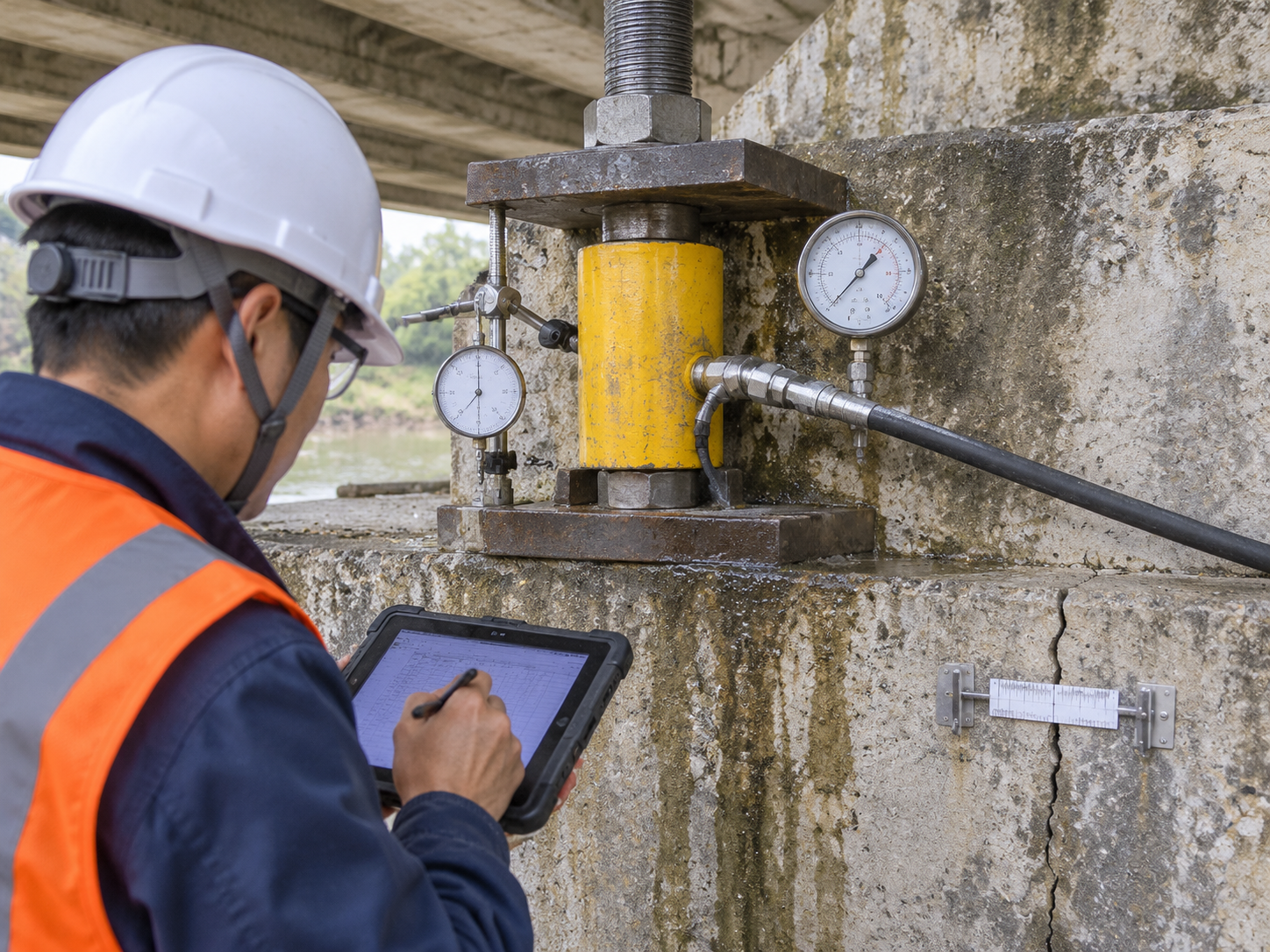
The test result is only one part of the record. A complete package includes the hole position and angle, the drilled length, the ground condition encountered, the grout mix and volume, the collar return, the plate seating, the torque applied, and the traceability of bar, coupler and grout batch. On a bridge, the package should also include the monitoring records for the structure during the works.
Three failure patterns recur. Grout escapes into voids and the anchor is short of cover. The bar is drilled past the intended bearing stratum and the fixed length is wrong. The plate is seated on spalled concrete and the load is transferred into a weak surface layer rather than the structure. All three are visible in the records before they are visible in a test.
What to Specify Before Ordering
The procurement checklist for a bridge project is short, but each line changes the price and the programme.
- Bar diameter and grade, matched to the drill, the access and the design load.
- Bit type and diameter, with a rule for what happens when the ground differs from the drawing.
- Coupler capacity and the maximum length that can be handled in the available headroom.
- Plate size and seating detail for stone, spalled concrete or a new jacket.
- Corrosion class for the exposure and design life, including coating repair at couplers and plates.
- Grout type, strength at stated ages, and the acceptance rule for grout take.
- Test regime: frequency, proof load, hold period, movement criterion and action on failure.
- Documentation: mill certificates, test reports, method statement, monitoring plan and as-built records.
- Access equipment and containment for flush water and spoil.
Where This Is Heading
Two changes are visible in bridge rehabilitation. The first is equipment: compact rigs and low-clearance attachments are making one-pass anchoring possible in places where a standard drill could not reach. The second is evidence: digital drilling records, grout volume logging and as-built models are turning the anchor from a hidden item into an auditable one.
Both changes favour the same conclusion. The value of a self-drilling anchor in bridge work is not that it is stronger than a conventional bar. It is that the installation can be completed, recorded and defended. In a tunnel, a mistake can be seen and repaired. In an abutment, it cannot. That is why the specification, the monitoring and the record matter as much as the steel.
Related News
Other news you might be interested in

Self-Drilling Anchor Bolts for Water-Conveyance Tunnel Reinforcement
Self-drilling anchor bolts are useful for water-conveyance tunnel reinforcement when broken or water-bearing ground makes conventional drill-and-insert bolting difficult. By using a hollow threaded bar as both the drilling member and the permanent reinforcement, the system removes the separate bolt-insertion step and provides a channel for grouting through the same bar.For a water-conveyance tunnel, that installation advantage matters. Headrace, tailrace, diversion, irrigation and water-supply tunnels can pass through fault zones, weathered rock, weak interlayers and interconnected fractures. Groundwater may enter the excavation, boreholes may deteriorate after drilling, and support must be coordinated with drainage, waterproofing and the final lining.

What Is a Split Set Mining System and How Is It Different from Other Rock Bolts?
A split set is often described as a rock bolt, but in mining it is more useful to think of it as a support system. The steel tube is the most visible part. The way it performs also depends on the drilled hole, the bearing plate, the installation adapter, the drilling equipment, the surface support and the checks made underground. That distinction matters when a project compares rock bolts. Two quotations can list a similar diameter and length, yet propose different load-transfer mechanisms, different hole requirements and different installation procedures. A split set is not a resin bolt with the resin removed. It is not a mechanical expansion-shell bolt, a self-drilling hollow bar, a water-inflatable tube or a cable bolt. Each product family solves a different part of the ground-support problem.
Want to know more?
Get in touch with us for more information about our services and products.