

Where a Rock Bolt Fails Matters: Reading Failure Location in Underground Support

Dayang Yang
AuthorWith over 15 years of experience in the production and sales of ground anchoring and mining support products, we operate our own rock bolt and accessory manufacturing facility with stable large-scale production capacity. We are specialists in rock bolts, resin cartridges, anchor cables, bearing plates, and customized ground anchoring products for mining support and geotechnical anchoring solutions.
A failed rock bolt is often described in one sentence: the bolt broke, pulled out, or came loose. That description records an outcome, but it does not explain the problem.
The location of the failure is more useful. Did the steel rupture in the bar body, at the thread, inside a coupler, behind the plate, at the resin–rock interface, or in the rock mass itself? Did the bolt survive the ground movement but lose surface restraint when the plate punched into weak rock? Did a delayed fracture begin at a corroded pit far from the collar?
Those are different load-path events. They point to different parts of the support system and require different evidence before anyone can decide whether the cause was material, design, installation, environment, loading, or a combination.
This article explains how mining and tunneling teams can read failure location in underground support. It is written for rock-mechanics and geotechnical engineers, contractors, supervisors, quality personnel, and technical buyers who need to turn a failed bolt into useful engineering information rather than an immediate argument about product quality.
A failure location is evidence, not a verdict
A rock bolt does not perform on its own. It is part of a load path:
- the surrounding rock;
- the borehole and anchorage material;
- the bar and its surface profile;
- threads, couplers, or other connections;
- the plate, nut, washer, mesh, strap, or other surface-support elements.
Failure occurs where the demand exceeds the capacity of one part of that path, or where deformation has made the system unable to perform its intended function.
The failure location tells us where the system reached a limit first. It does not, by itself, tell us why that limit was lower than expected. A thread fracture could follow tensile overload, a cut-thread stress concentration, bending, corrosion, or installation damage. A bond failure could reflect a short encapsulated length, a contaminated hole, resin loss, weak rock, or a test arrangement that forced failure at one interface.
The useful sequence is therefore:
- Locate the failure.
- Describe the failure mode and deformation.
- Reconstruct the installed system.
- Compare it with the design and installation records.
- Identify the evidence still needed.
Map the support-system load path
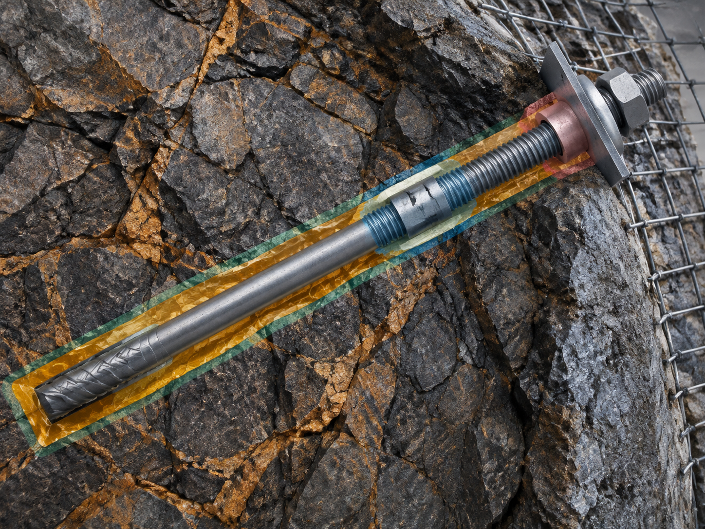
Before interpreting a failed component, it helps to separate the possible failure zones.
| Zone | What it includes | Question raised by a failure there |
|---|---|---|
| Bar body | The main steel section between the anchor and the collar | Was the bar subjected to axial tension, bending, shear, corrosion, or a combination? |
| Thread or end connection | Threaded end, nut engagement, coupler, or adaptor | Was the connection the weakest part of the specified assembly? |
| Plate and collar | Plate, washer, nut, and rock surface behind the plate | Did the plate lose contact, punch into rock, or fail under eccentric load? |
| Bar–grout/resin interface | Contact between the bar and the anchorage material | Did the bar pull or slip through the bond zone? |
| Grout/resin–rock interface | Contact between the anchorage material and borehole wall | Did the bond separate from the rock, or did the rock surface fail? |
| Grout or resin body | The cured material in the annulus | Was the annulus continuous, mixed, cured, and confined? |
| Surrounding rock | The rock mass that receives the load | Did the bolt transfer load successfully into a rock mass that then failed? |
These zones are connected. A strong bar can be limited by its thread. A good resin can be limited by a contaminated borehole wall. A well-installed bolt can be limited by a plate punching into weak surface rock. A high-capacity support element can be defeated by a rock mass that cannot provide confinement.
Bar-body failure: tensile, bending, or shear?
A fracture through the bar body is often described as a tensile failure, but the fracture appearance and the surrounding geometry matter.
Under predominantly axial tension, a ductile steel bar may show visible elongation or necking before fracture. A cup-and-cone fracture surface can be consistent with ductile tensile overload in a suitable test. In a roof or wall, however, the failed bar may also have been bent, sheared, or subjected to repeated loading before final rupture.
The article should not turn a fracture-surface description into a remote diagnosis. A laboratory tensile test can show a clear load-displacement curve and a controlled fracture. A service failure may involve several mechanisms acting together.
Useful questions include:
- Was the fracture in the free length, within the bonded length, or close to the collar?
- Was the bar straight, bent, or deformed at the failure?
- Was there visible section loss, pitting, or coating damage?
- Did the failure occur after installation, during loading, or after a period in service?
- Was the surrounding rock displaced, broken, or quiet at the time of failure?
The location tells the investigator where to look next. It does not yet separate material strength from ground movement.
Thread and connection failure: the weak link can be intentional or unintended
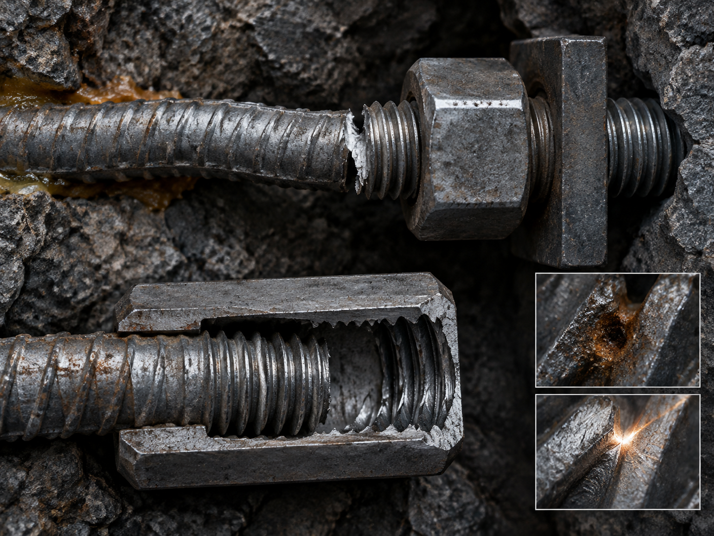
Threads, couplers, and adaptors are common locations for rock-bolt failures because they interrupt the continuous steel section and introduce stress concentrations.
In general rock-engineering guidance, coarse rolled threads are preferred over fine cut threads in typical underground conditions. A cut thread removes material and can create a stress concentration; failures have been observed at the first thread behind the nut. A rolled thread is not immune to failure, but the manufacturing method and thread geometry matter.
The failure may be:
- tensile rupture through the threaded section;
- thread stripping or insufficient engagement;
- coupler fracture;
- bending or shear at an offset connection;
- corrosion at exposed threads or behind the nut;
- damage from handling, installation torque, or equipment.
This is why the phrase “same diameter” is not a compatibility statement. A coupler or threaded connection must match the bar system, thread form, engagement length, material condition, and installation requirements. A joint that can be threaded together by hand has not demonstrated that it can carry the specified load.
When a failure occurs at a connection, preserve:
- the mating bar end and coupler;
- the engaged and unengaged thread length;
- the fracture or stripped surfaces;
- whether the failure was axial, bending, or shear;
- the assembly drawing and material records;
- any evidence of corrosion, damage, or misalignment.
The location raises the possibility of a connection limit. The evidence must show whether the connection was appropriate and whether it was installed as intended.
Plate and collar failure: when the surface loses the load path
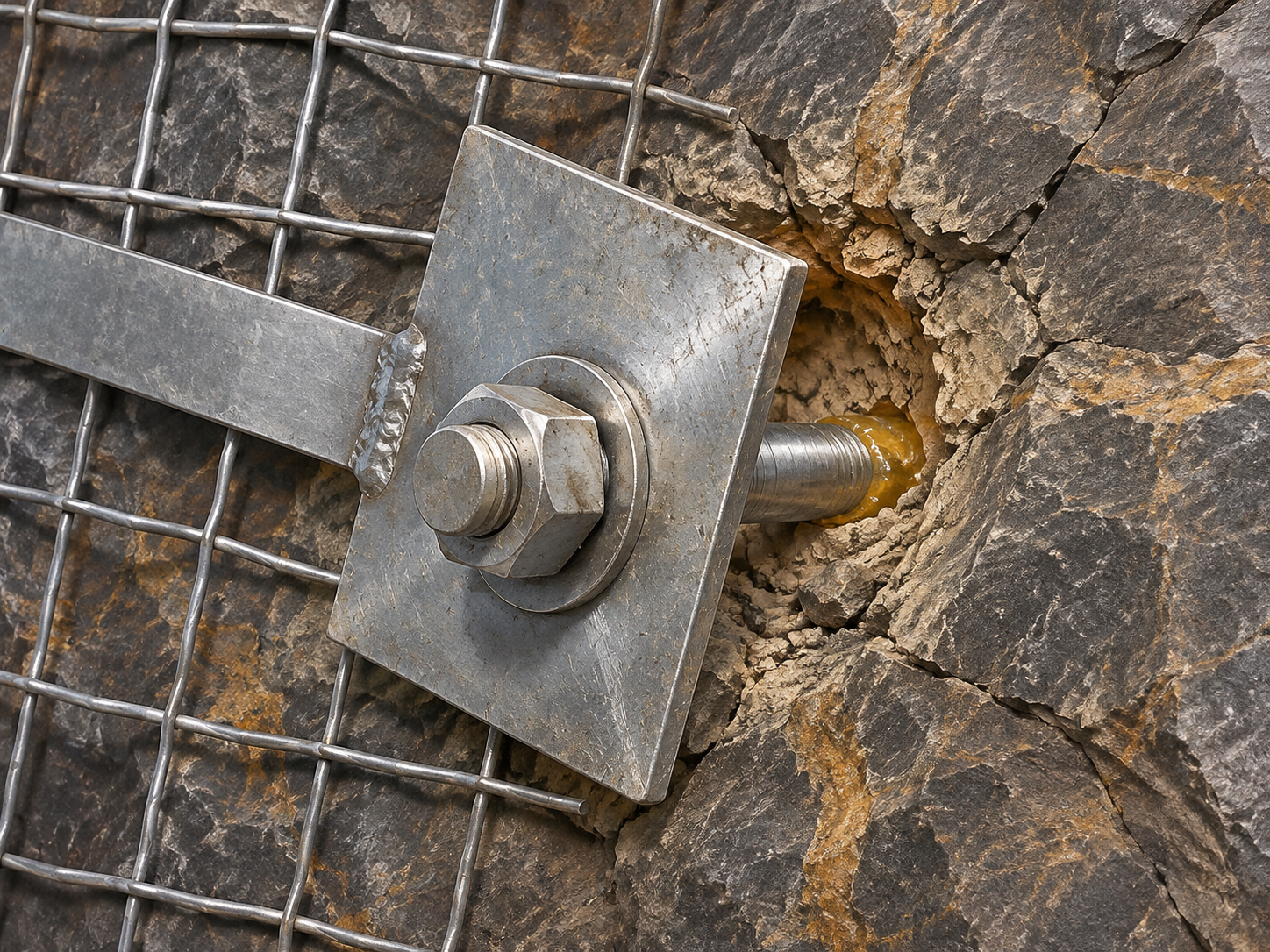
The plate and nut transfer load from the bolt to the rock surface and the surface-support system. Failure at the collar can occur in several ways:
- the nut loses engagement or strips;
- the plate deforms or cracks;
- the plate punches into weak rock;
- the plate seats on an irregular surface and loads eccentrically;
- the bolt pulls through the plate or washer;
- the plate loses contact after rock surface degradation;
- the connection to mesh, strap, or other surface support is inadequate.
A plate that is visibly tight immediately after installation may not remain in contact after the rock surface relaxes, spalls, or erodes. A plate that appears to have failed may have been reacting to a surface rock failure rather than initiating it.
The collar is also exposed to water, air, handling damage, and sometimes aggressive groundwater. Corrosion of the plate, nut, or the first exposed threads can reduce the effective connection even when the encapsulated bar remains protected.
The important distinction is between:
- failure within the plate–nut–bar connection;
- failure of the rock immediately behind the plate;
- loss of contact caused by larger ground movement;
- failure of the surface-support system connected to the plate.
Each produces a different inspection and design question.
Bond failure: which interface let go?
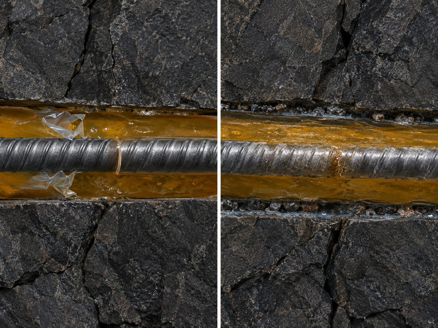
For resin- or grout-anchored bolts, a pull-out failure does not identify a single interface by itself.
The bond path has two principal interfaces:
- Bar–resin/grout interface. The anchorage material slips relative to the bar.
- Resin/grout–rock interface. The anchorage material separates from the borehole wall, or the wall material fails.
The grout or resin body can also fail in shear, and the surrounding rock can fail before either interface reaches its limit.
Research and field investigations show that the governing location depends on the system and ground. In some short-encapsulation tests, the bolt–grout interface governed; in others, failure occurred between the resin and rock. In one field study, the push tests failed predominantly at the resin–rock interface. These are not contradictory results. They show that a different combination of bar profile, hole diameter, rock, resin, and test arrangement can change which part of the load path is weakest.
The failure location is useful because it tells the team which interface to examine:
- For a bar–resin failure, review bar surface profile, resin adhesion, mixing, gloving, and insertion.
- For a resin–rock failure, review hole-wall condition, rock strength, drilling method, water, fines, and resin loss.
- For cohesive failure through the resin, review material strength, annulus geometry, curing, and confinement.
- For rock failure, review the rock mass, confinement, stress, and the volume engaged by the anchorage.
The location narrows the question. It does not prove that the named component was defective.
Rock-mass failure: the bolt may have transferred load successfully
Sometimes the bolt remains intact while the rock behind the plate or around the anchor fails. This can produce a crater, a pulled-out block, or a zone of broken rock around the anchorage.
That pattern may indicate that the bolt transferred load into the rock as intended, but the rock mass was unable to carry it. It may also indicate that the anchorage length engaged a weak or fractured zone, that the support pattern was inadequate for the block size, or that the ground changed after installation.
Rock-mass failure should not be treated as proof that the bolt is strong enough or that the support design is adequate. It means the next investigation must include the geology, jointing, stress, excavation sequence, and surface-support system—not only the failed steel.
Corrosion and delayed failure: the break may not look like the beginning
Corrosion can reduce the effective steel section and create a initiation point for fracture. In aggressive groundwater, pitting may be localized; under sustained tensile stress, stress-corrosion cracking can cause premature failure of high-strength rock bolts.
A 2025 laboratory study of stress-corrosion cracking in simulated underground environments found that different steel microstructures had different susceptibility under the tested conditions. The cracks initiated at stress concentrations in the test specimens.
This does not mean every broken bolt is a stress-corrosion failure. It means the visible fracture location may not be the start of the failure process. A fracture surface, corrosion deposit, and exposure history need to be examined together.
Delayed failures deserve particular caution when:
- the bolt was exposed to water or aggressive groundwater;
- the failure occurred months or years after installation;
- there is little or no visible necking;
- the fracture began at a corroded pit, thread root, or connection;
- the steel grade, coating, and environmental exposure are not fully documented.
The location can direct attention to a corrosion-sensitive detail, but a material or corrosion diagnosis requires appropriate laboratory evidence and qualified review.
Dynamic and shear loading change the failure map
In deep or high-stress mines, a bolt may experience axial loading, shear across a joint, bending, or a combination. A support element designed to carry static axial load may behave very differently under rockburst, fault slip, or large deformation.
A strong bar can fail with little deformation if the system is too stiff for the ground movement. A bolt with high elongation but weak surface restraint may permit rock ejection between bolts. An apparently intact bar may have lost anchorage because the resin or rock failed at the bond zone.
This is why “the bolt broke” is not enough to evaluate dynamic performance. The relevant evidence includes the loading direction, the displacement, the condition of the plate and mesh, and the failure location along the support system.
Recent product development reflects this systems view. Normet’s 2026 HX-Bolt announcement describes immediate mechanical/frictional support followed by optional resin or grout encapsulation, while Sandvik’s 2026 xCell announcement describes monitoring of installed bolt condition over time. These are manufacturer-specific developments and do not prove CQ product capability, but they illustrate why installation state, load history, and long-term condition must be considered together.
How to preserve failure evidence
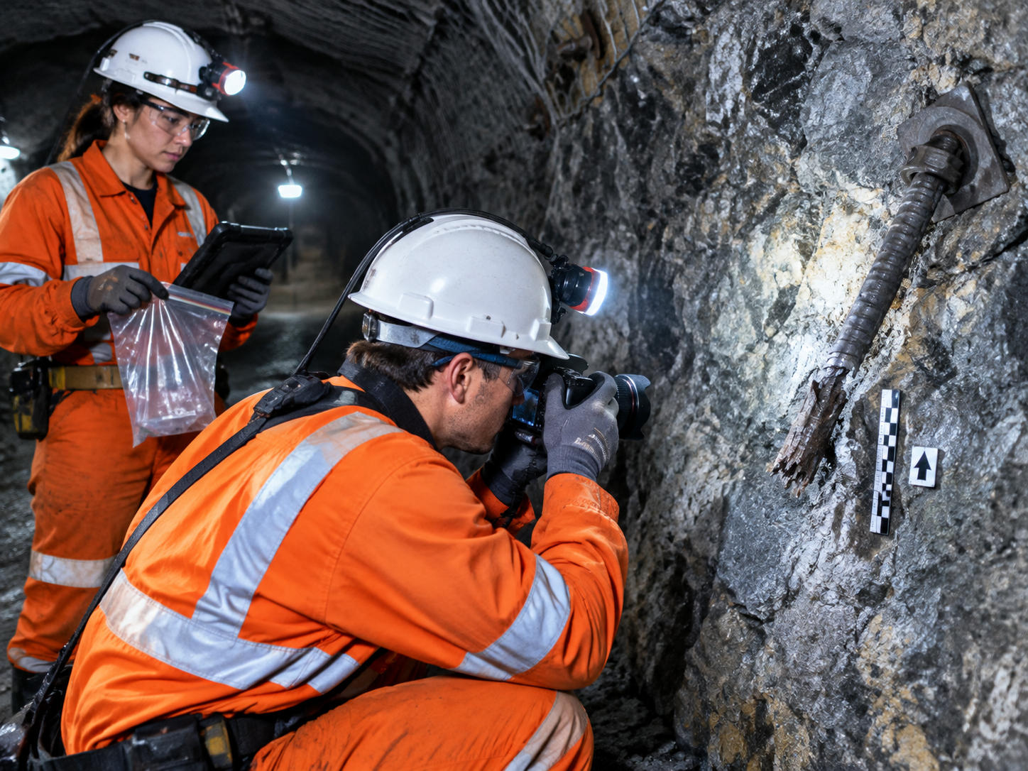
A useful failure investigation begins before the broken parts are discarded or cleaned.
Record:
- the exact location of the failure in the support pattern;
- the orientation of the bolt and the opening;
- photographs with a scale and a clear view of the fracture surface;
- whether the bar was bent, necked, corroded, or damaged;
- the position of the plate, nut, washer, and surface-support components;
- the condition of the rock behind the plate and around the hole;
- the borehole diameter and condition where it can be recovered;
- the bolt type, diameter, thread, coating, and heat or batch identification;
- the resin or grout product and cartridge details;
- installation date, equipment, spin and hold records where available;
- water, groundwater chemistry, and environmental exposure;
- loading, blasting, seismic, or ground-movement history;
- the test or inspection results that had previously been accepted.
Do not clean the fracture surface aggressively before photographs and specialist review. Do not assume that the first visible break is the origin of the failure.
What the location cannot prove
A failure location should narrow the investigation, not end it.
It cannot, by itself, establish:
- that the steel chemistry was wrong;
- that the resin or grout was defective;
- that the installation was incorrect;
- that the ground condition exceeded the design;
- that the product was suitable or unsuitable for another project;
- that the support system would have performed differently under another loading condition.
Those conclusions require the product specification, installation record, ground information, exposure history, test evidence, and failure examination to agree.
The useful question is not “which component looks guilty?” It is:
Which part of the support system reached its limit first, under what loading and environmental conditions, and what evidence is needed to explain why?
When a failure is investigated in that order, the result can improve the next support decision. It can reveal a thread detail to revise, a plate contact problem to correct, a borehole condition to control, a testing scope to expand, or a ground condition that was not represented in the original design.
Conclusion: read the location before assigning the cause
A rock bolt failure is a system event expressed at a particular location. The bar, connection, plate, bond interfaces, grout or resin body, and surrounding rock all participate in carrying load.
The location of failure tells engineers where the load path stopped working as expected. It does not identify the cause without the surrounding evidence. Reading the location correctly is therefore the first step toward a better technical investigation—and a better next support decision.
Need a project-specific review?
CQ Rockbolt supplies rock bolts, resin anchoring materials, prestressing components, and related ground-support products for underground mining and tunneling. If you are reviewing a failure or planning a support change, provide the bolt type and drawing, thread or coupler details, plate and surface-support arrangement, borehole and ground conditions, installation records, exposure history, and available test information. The evidence can then be reviewed against the actual system rather than a single photograph of a broken component.
Related News
Other news you might be interested in

Water in the Borehole: Why a Resin Bolt Can Be Installed but Still Fail to Anchor
A resin bolt can pass every visual test at the collar and still fail to develop the anchorage expected by the design. The bolt may be in the hole, the plate may be tight, and resin may be visible at the surface. None of those observations proves that the resin filled the intended bond length, mixed properly, or formed a sound interface with the rock.

Resin Anchor Bolt Anchorage Force Formation: Resin Annulus Thickness, Mixing Quality and Interfacial Bonding
A resin anchor bolt is often evaluated as though anchorage were a single number printed on a resin cartridge. In service, anchorage is a load path. The bolt must grip the resin, the resin must remain continuous and sound, the resin must grip the borehole wall, and the rock must accept the load. A weakness anywhere in that chain changes the result, even when every component meets its own specification.
Want to know more?
Get in touch with us for more information about our services and products.